| HIFI-FORUM » Stereo » Elektronik » Röhrengeräte » Schematics, Dynavox VR70E 2 | |
|
|
||||
Schematics, Dynavox VR70E 2+A -A |
||||
| Autor |
| |||
|
tri-comp
Stammgast |
#1
erstellt: 07. Apr 2007, 13:14

|
|||
|
Hi, I just finished the first part of drawing the schematic diagram of the Dynavox VR70E 2. So far the Left amp. is drawn and the power-supply will be next. The drawing is made from the fax-copy I received from the German importer and from looking directly at the amplifier. The fax had several errors and they should hopefully be corrected now. Comments and corrections are welcome. -> http://img247.imageshack.us/my.php?image=vr70e2leftampop7.jpgThanks for all good posts in this thread. I enjoy reading all your comments. Kind regards, /tri-comp |
||||
|
E130L
Inventar |
#2
erstellt: 07. Apr 2007, 15:01
|
|||
|
Hi tri-comp, welcome in the HIFI-Forum, a VR70 wiring diagram made by another forum user you find here: VR70Ekindly regards Volker |
||||
|
|
||||
|
tri-comp
Stammgast |
#3
erstellt: 07. Apr 2007, 20:08
|
|||
|
Hi, Yes, I know about this schematic. It's for the VR70E first version. My schematic is for the second version VR70E 2. I don't think I saw it anywhere before. The power-supply schematic will be ready to upload soon. Just need to check everything one extra time  Kind regards, /tri-comp |
||||
|
tri-comp
Stammgast |
#4
erstellt: 07. Apr 2007, 22:35
|
|||
|
Dynavox VR70E 2 Power-section schematic. -> http://img154.imageshack.us/my.php?image=vr70e2powerlj0.jpgPlease excuse me for writing in English. I read German well enough but I'm not able to write any good. Now, I'll re-assemble my new Dynavox and fire it up for the first time. Should be interesting Kind regards, /tri-comp [Beitrag von tri-comp am 07. Apr 2007, 22:37 bearbeitet] |
||||
|
dr0mabuse
Neuling |
#5
erstellt: 14. Dez 2018, 05:00
|
|||
|
sorry but it is no more possible to download the picture - Error 404. Could you please give another fownload link? thanks Jochen |
||||
|
tri-comp
Stammgast |
#6
erstellt: 14. Dez 2018, 07:49
|
|||
|
Hi Jochen and everyone, My Dynavox is still doing very well and running on original EL34 tubes. I haven't modified the amplifier in any way as I'm quite happy with it the way it's built originally. Here again are the schematics for the amplifier as I made them 11 years ago. Have a Merry Christmas, Best regards, /Torben LEFT CHANNEL AMPLIFIER:  POWER SUPPLY 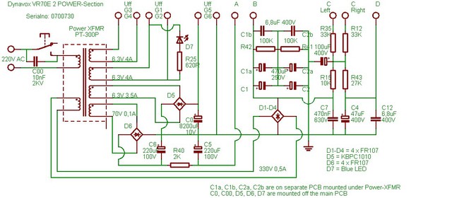 |
||||
|
sweetfred
Neuling |
#7
erstellt: 27. Dez 2018, 22:05
|
|||
|
Hi Torben I really cant read your pretty drawings so I must ask, the simple mods suggestef in the old thread for the first version of this amp (wo riia); are any of them now implemented from the factory? The problem with the input, with the redundant componant, is it there still? Also on the phono in? Sorry for being electricly illiterate. Happy new year! / fred [Beitrag von sweetfred am 27. Dez 2018, 22:07 bearbeitet] |
||||
|
tri-comp
Stammgast |
#8
erstellt: 28. Dez 2018, 01:13
|
|||
|
Hi Fred, I'm afraid I don't quite understand what you mean. The only production difference that I know of between the first and the second versions of the amplifier is the addition of a capacitor sub-board in the newer version containing C1a/C1b and C2a/C2b in my schematic, picture attached. Redundant parts in the input is a matter of opinion. You could replace C15/C18 with shorting links and remove R17/R22. I believe I've seen it suggested somewhere, possibly here; I don't remember. If you do it, theoretically you'll extend the low-frequency response downwards but at the same time you'll depend on the volume-control as a gridleak to ground. This is NOT a good idea at least with the original potentiometer. This is in fact the only component so far that doesn't function like new in my amplifier. Dust and/or corrosion makes the potentiometer noisy in the amp. and at the same time it'll be a VERY unstable grid-leak for the input tube. As for these modifications or other I haven't done any of them to my amplifier. That isn't to say I wont at some time in the future. I have the necessary measuring equipment and possibly also the knowledge to do some improvements. I simply don't have the time at the moment to investigate the options but retirement is getting closer 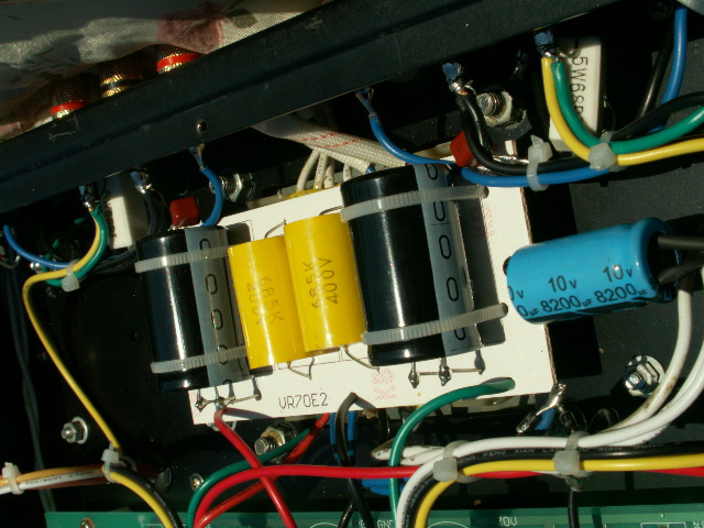 Best regards, /Torben |
||||
|
DB
Inventar |
#9
erstellt: 28. Dez 2018, 13:03
|
|||
|
Hallo,
im Schaltplan fehlt der Anodenwiderstand der Katodynstufe.
Die Kondensatoren C4, C12 sowie der Kondensator rechts neben R41 reichen spannungsmäßig nicht aus. C5, C6 sind äußerst knapp bemessen, bei den zu veranschlagenden 10% Netzüberspannung reichen die auch nicht. Antiparallel zu D7 sollte man eine Diode vorsehen. MfG DB |
||||
|
tri-comp
Stammgast |
#10
erstellt: 28. Dez 2018, 18:53
|
|||
|
Hello, I don't disagree with your points about the capacitors having a too low voltage-ratio. Here, more is better. It hasn't been necessary to replace the cap's in my amp. yet, but when/if it becomes necessary I shall of course select cap's with a higher voltage rating. The power-LED should have a rectifier diode in anti-parallel, but it hasn't and it still works fine. Perhaps the specified PIV (Peak Inverse Voltage) is sufficiently high ? Impossible to know with unknown Chinese parts... You are however not correct in saying the anode-resistors are missing in the cathodyne phase inverter. They are drawn as a part of the power-supply schematic (R12/R35). NOT because I found it very normal to do so, but because the ORIGINAL schematic diagram, that I received from the German company where I bought the amplifier, and was received in a VERY BAD COPY submitted by FAX, is drawn in this way. I reasoned that if someone got used to seeing the original schematic I should draw my version in a similar way. MfG /Torben [Beitrag von tri-comp am 28. Dez 2018, 18:54 bearbeitet] |
||||
|
*Tubeli*
Ist häufiger hier |
#11
erstellt: 19. Feb 2019, 12:32
|
|||
|
Hello Torben, You asked about improvements ... Of course you can modify/improve everything, BUT it should make sense and should also fit into the context/range. The VR70 has not the worst circuit-topology nor does it have the worst output transformers. Both are OK and perfectly represent the price-performance-ratio of the amp which is quite moderate/low. It will not make too much sense to optimise the whole circuit without replacing the transformers and afterwards heavily modifying the whole circuit to get rid of the Katodyn-driver-stage, which is not the best to drive higher PP-signals like here in a fixed-bias-higher-Vg1-application. You see, useful and senseful mods/improvement have limits here. I personally would not do too much to this apparatus. If you have some measuring equipment, you may balance the Katodyn-stage in terms of high-frequency respective equal output/driving impedance. This is very easy and just affords one resistor in the Katodyn-kathode-follower-signal-line. Just take the resistor value which will create the very same high-frequency spectrum on both outputs of the Katodyn-stage. I had quite a lot VR70's here for service/repair/maintainance over the years. Compared to the early ones the VR70 has become much better. The obvious circuit copying mistakes have gone, the whole thing now (besides of some undersized component values) is technically clean. To get rid of the slightly-too-high B+ voltage there are many ways. I often used a simple R-C-filter (only one resistor) in the power-supply between D1/D4-C1/C1a. This will do the job and is sonically not detectable (for me) ;-) Marcus [Beitrag von *Tubeli* am 19. Feb 2019, 12:35 bearbeitet] |
||||
|
tri-comp
Stammgast |
#12
erstellt: 19. Feb 2019, 13:36
|
|||
|
Hi Marcus, I totally agree with you posting. In many amplifiers, as in this, the phase-inverter is a critical point that could be improved upon. Since this is an amplifier built on a PCB it's not so easy to do experiments in order to improve the performance. I do have on hand a FFT spectrum analyzer besides vintage equipment like a HP 302A Wave Analyzer for measuring harmonic and IM distortion. What I don't have on hand is time In a foreseeable future, however I will retire and hopefully have lots of spare time on hand. Then it'll be interesting to see what can actually be done to this amp., short of replacing the transformers. Thank you for your reply and thoughts. Mfg, /Torben |
||||
|
*Tubeli*
Ist häufiger hier |
#13
erstellt: 19. Feb 2019, 13:42
|
|||
|
Torben, Two resistors, one around 30-40k and the other around 47 Ohms/9W should not be too time consuming. Further I would let this apparatus stay like it is. Marcus |
||||
|
tri-comp
Stammgast |
#14
erstellt: 19. Feb 2019, 13:59
|
|||
|
Marcus, It's not the time to do the modifications I'm worried about. It's the follow-up with measuring and tweaking that's going to be time consuming. Don't worry, I'll get there eventually..... /Torben |
||||
|
*Tubeli*
Ist häufiger hier |
#15
erstellt: 19. Feb 2019, 14:14
|
|||
|
Sorry Torben, but what was your intension for this thread ... ? No time, no effort, just talking ??? BTW, drawing the schematic was much more time consuming ... ;-) If you have no time, you may send the VR70 to me and I will do the mods for you, if you like. Marcus [Beitrag von *Tubeli* am 19. Feb 2019, 14:17 bearbeitet] |
||||
|
tri-comp
Stammgast |
#16
erstellt: 19. Feb 2019, 21:18
|
|||
|
My intention with this thread, which should otherwise be clear from the title, was to give to this community up-to-date schematics for the VR70E-2 around the very time it was introduced. I received the amplifier from Germany and took it apart immediately, even before applying power to it, in order to reverse-engineer the circuit. Having done that I drew the schematics and posted them. I assumed someone would be gratefull. I know I sure would if someone did me a favour like that. Especially since only schematics for the original VR70E were available on-line to my knowledge. Besides, as I know my way well around electronics, having been an electronics repair tech for more than 40 years, there's quite a big chance that my schematics are valid and w/o errors. Thank you Marcus, but I'm not going to let someone take away the fun of modifying the amp. by shipping it out of my country (Denmark) to have it upgraded. I reserve that pleasure for myself at my old age  mfg, /Torben |
||||
|
DB
Inventar |
#17
erstellt: 20. Feb 2019, 11:12
|
|||
|
Hallo,
VR ist bei LED (5 ... 7)V, insofern sollte auch davon ausgegangen werden, daß das hier so ist.
In der Tat, die Widerstände sind vorhanden. Die Schaltung ist in einer äußerst unüblichen Art und Weise gezeichnet, auch im Hinblick auf Leitungskreuzungen und -verbindungen. Beim Nachzeichnen hättest Du das doch bequem korrigieren können.  MfG DB |
||||
|
tri-comp
Stammgast |
#18
erstellt: 21. Feb 2019, 16:50
|
|||
|
Yes, I could have chosen to draw the schematic in a more sensible way, and I have already told you why I didn't. I'll attach a copy of the original schematics diagram I received by fax from the dealer in Germany in 2004. As you'll notice the anode-resistor on the phase-inverter has been drawn as a part of the power-supply, just like I did. NOT a very common way to draw the inverter, but everything is there and it's just a matter of connecting-the-dots Mfg, /Torben 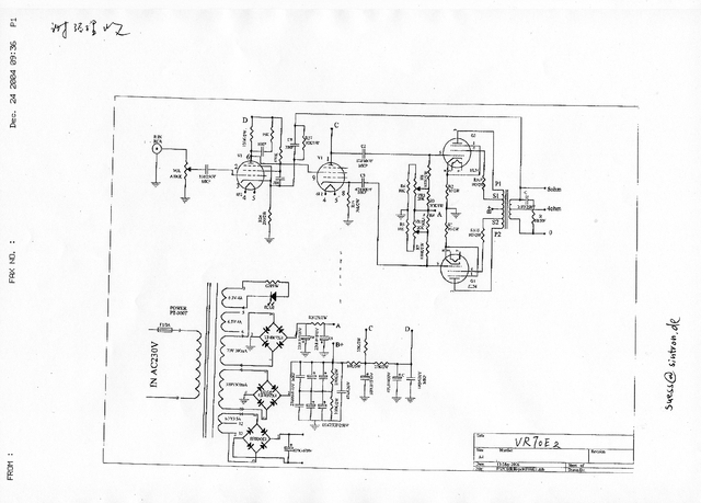 |
||||
|
Eduardo-AAVM
Neuling |
#19
erstellt: 23. Jun 2023, 20:10
|
|||
|
Hallo ! Guten Tag aus Mexiko Haupstatd ! Ich habe ein einfach Frage für sie: Können VR-70E II oder TAC 34 für 120V AC konvertiern ? Ab so, was muss Ich Machen ? Proßt ! |
||||
|
tri-comp
Stammgast |
#20
erstellt: 23. Jun 2023, 22:13
|
|||
|
Hi, In my opinion the fact that you ask how, is in it self telling a conversion will probably not be something, you are able to do yourself. Obviously it will require a new mains transformer with a 120V primary winding. The secondary windings will all stay the same. To find someone willing and able to make one will be challenging OR you may obtain from the US. if this amplifier was sold there, an original transformer for 120V AC primary. A simple way to solve the problem will be to insert a 1:2 step-up transformer between the 120V AC wall socket and the amplifier. 120V AC input and 240V output (could be 117V AC to 134V AC as well). It has to be able to supply enough energy to the amplifier so I would go with no less that 200Watt. Best regards / Mfg, /Torben [Beitrag von tri-comp am 23. Jun 2023, 22:15 bearbeitet] |
||||
| ||||

|
|
||||
| Das könnte Dich auch interessieren: |
|
Dynavox TPR1 schematics miljac am 22.03.2007 – Letzte Antwort am 03.04.2015 – 25 Beiträge |
|
Dynavox Vr70e Ruhestrom schankt Sondermann am 09.12.2010 – Letzte Antwort am 09.12.2010 – 3 Beiträge |
|
Dynavox VR70E-2 Röhren kaputt? uSSolider am 24.12.2009 – Letzte Antwort am 25.12.2009 – 3 Beiträge |
|
AÜ für "Dynavox VR70E-2" schirmgitter am 10.12.2016 – Letzte Antwort am 12.12.2016 – 8 Beiträge |
|
Dynavox VR70E - "knacken" bögrülü am 24.02.2006 – Letzte Antwort am 08.05.2006 – 29 Beiträge |
|
Dynavox VR70E Soeben abgebrannt cyberdevil am 08.12.2006 – Letzte Antwort am 13.12.2006 – 44 Beiträge |
|
Dynavox vr70e "Brummen" Simon1311 am 11.01.2008 – Letzte Antwort am 15.01.2008 – 12 Beiträge |
|
Dynavox VR70E Defekt? HifiMeo am 08.02.2009 – Letzte Antwort am 09.02.2009 – 5 Beiträge |
|
Dynavox VR70e Endröhre brennt durch T.B.71 am 08.03.2009 – Letzte Antwort am 09.03.2009 – 4 Beiträge |
|
NAD 3020 --> Dynavox VR70E-2 = Brummen! rrrock am 22.08.2006 – Letzte Antwort am 25.08.2006 – 7 Beiträge |
Foren Archiv
Anzeige
Produkte in diesem Thread


Aktuelle Aktion


Partner


Top 10 Threads in Röhrengeräte der letzten 7 Tage
- Voodoo oder nicht? Können neue Röhren einen derartigen Unterschied machen?
- Lua 4040 c Klang?
- Telewatt Restaurationsthread
- Trafobaule 300B-Kit: Erfahrungen, Meinungen?
- Masse, aber richtig !
- Meine erste Röhre - Amplifon WT30
- EL34 gegen 6P3S-E = 6L6GC = 5881 tauschen
- AMC CVT 3030, wie gut ist der?
- Audio Note P-Zero Monoendstufen
- Octave Röhrengeräte Thread .
Top 10 Threads in Röhrengeräte der letzten 50 Tage
- Voodoo oder nicht? Können neue Röhren einen derartigen Unterschied machen?
- Lua 4040 c Klang?
- Telewatt Restaurationsthread
- Trafobaule 300B-Kit: Erfahrungen, Meinungen?
- Masse, aber richtig !
- Meine erste Röhre - Amplifon WT30
- EL34 gegen 6P3S-E = 6L6GC = 5881 tauschen
- AMC CVT 3030, wie gut ist der?
- Audio Note P-Zero Monoendstufen
- Octave Röhrengeräte Thread .
Top 10 Suchanfragen
Forumsstatistik
- Registrierte Mitglieder931.203 ( Heute: 5 )
- Neuestes MitgliedSonia
- Gesamtzahl an Themen1.564.951
- Gesamtzahl an Beiträgen21.873.133
