| HIFI-FORUM » English » DIY (Engl.) » Santa Claus DIY Tube Amp | |
|
|
||||
Santa Claus DIY Tube Amp+A -A |
||
| Autor |
| |
|
screamgigi
Stammgast |
#1
erstellt: 14. Okt 2006, 10:11

|
|
|
It is that time of the year when the urge to make one last amplifier starts kicking in. Weather starts getting fine; you can sit outdoors and solder. This is the ideal time to embark on yet another project. You will be ready by the Christmas bragging season when hopefully the new creation will belt out music with the valves glowing warm. Thanks to the Mod boss we now even have a DIY section, and what better than keep posting the progress. So if the fellow posters and Mod indulge, I very immodesty offer to build and test a power amp while sharing the outcome in this section. How does this idea sound? If yes then we need to decide on the following, which will enable us to progress forward. 1. How Much PO 2. Valve or Solid State. 3. Monoblock or a Stereo build. Once the above 3 main criterion have been establish we shall explore topologies, components etc. Looking forward to opinions. [Beitrag von screamgigi am 14. Okt 2006, 10:13 bearbeitet] |
||
|
Amp_Nut
Inventar |
#2
erstellt: 14. Okt 2006, 16:30
|
|
|
Hi screamgigi, That IS a VERY generous offer. Knowing you high skill & knowledge levels, I am tempted to suggest a couple of ambitious projects: 1. A Valve Power Amp.  2. To make it different from run off the mill, a power output of atleast 100 Watts ( RMS ) per channel. 3. Maybe an OTL Valve amp, or one using 845 tubes (Non OTL) 4. Monoblock if necessary for size requirements.  I agree, this may not be the mass appeal DIY... |
||
|
|
||
|
screamgigi
Stammgast |
#3
erstellt: 14. Okt 2006, 17:52
|
|
|
Thanks Amp_Nut-ji. I am glad to recive your approval. I know that you will contribute solidly to this build. But you have set the goal post so far, high and deep for my amateurish skills  Lets examine your suggestions. 1.A Valve Power Amp. Why not ??  2.To make it different from run off the mill, a power output of atleast 100 Watts ( RMS ) per channel. The only issue I foresee is the output transformer and the cost. Let me research this. Honestly I have never made a valve amp bigger than 50 watts. And that was for a guitarist. 3. Maybe an OTL Valve amp, or one using 845 tubes (Non OTL) Interesting suggestion ! OTL is something I have been wishing to do for a long time. As for the 845, right now I am restoring a pair. I do have a spare set of Japanese Output transformers suitable for 845 in SE. The only issue is the power transformer and chokes. I would like to mention that I import all my ironware. Another worry I have is that an 845 will take a long time to finish and frankly I dont have space for 2 pairs of 845 amp at my home 4. Monoblock if necessary for size requirements. Most certainly yes. This is my preferred option too. So I think we are getting down to two things as of now. 1.Valve power amp 2.Monoblocks Now we need to decide a power requirement. While doing so we shall be guided by ease of building, maintenance, cost etc. What if I suggest: 1.Power rating between 18 to 22 watts RMS /channel in pure Class A. This is a reasonable choice. Anything more will require a substantially higher layout and complications. And I feel for most practical purposes we are well served by around 45 watts of Class A valve power. 2.Use EL34/6L6/KT66/807 tubes for output. I have built amps with all the above tubes, and today 100% endorse the older coke bottle shape 6L6G or the 807. I will save the EL34 and KT66 for bragging times. Tubes will be wired in UL connection. 3.Use 6SL7 and/or 6SN7s for the input and splitter. Classic selection. Though I personally veer around to a pentode input stage. 4.Choke power supply Obviously superior. Will add to the cost and weight of the amp. We shall not shy away from using new fangled Solid State wherever possible. Therefore: 1.Silicon rectifiers. One could write a treatise on what is better; vacuum rectifier or silicone. Our heart says Valve but the ever modernistic head says SS. I am open to suggestions on this. Cost factor is marginally high in Valve rectifier. 2.Solid State CCS at the tails of splitter and to maintain the bias of output tubes. 3.We will employ SS to precisely control the behaviour of the tubes. Believe me; if the designers 50 years ago had access to SS devices they would have done the same too. We have more options: 1.EL84 based push pull amp. Expect around 12WPC in Class A 2.811A based SET. Anything between 9 to 15 WPC. Mind that top cap though! 3.845 based SET. Approx 22~22 wpc. Not to inclined to take up currently. Or 4.Solid State; Class A JLH. Truly a fine performer. 5.Gain Clone. Before I am beaten to pulp, let me hasten and add that a valve buffered GC sounds really fine. The overriding criteria will be: 1.Should be up an running within 2 months time. Remember Christmas happens around Dec 25th 2.Simple to build. Should inspire more people to take up DIY 3.Stay within a budget of Rs. 35 to 40K in case of a valve amp. 4.If using valves, we shall run them conservatively. They need to out live us. Comments. [Beitrag von screamgigi am 14. Okt 2006, 18:31 bearbeitet] |
||
|
Manek
Inventar |
#4
erstellt: 15. Okt 2006, 07:45
|
|
|
this sounds very very interesting ! Santa Claus is building an amp ! Screamgigi, How would you source the parts ? you have someone who can source them for you ? Manek. |
||
|
screamgigi
Stammgast |
#5
erstellt: 15. Okt 2006, 08:32
|
|
|
I hope it turns out simple and dandy. I also expect that by the time it is done some of the mysticism on valve amp building is thankfully cleared. They are after all not rocket science and if a dumb fellow like me can build them then so can 90% of posters here. I source parts from various places. Capacitors Elcos: Keltron India. Paper in Oil caps: I think India is the best place for that. Almost all old time radio part shop will have a bunch of them. All in NOS condition in box. Cornell Dublier, Sprague, Sangamo, TCC. Everything is available. Coupling Caps: I either use Sprague (as above) or use MKP depending upon the application. Metalised Polyprops are sourced from Far East. Lately I have been using Arcotronics. I had an email exchange with Thorsten who claimed they were the best he could test. Resistors A mix of NOS Carbon Composition and modern Metal Films. Sourced in India. Transformers Japanese make the best Output transformers. I bought a couple of pair from Tango and Hashimoto. Unfortunately, they are way beyond expensive. I then discovered a Korean company who made to exact Tango spec but 1/3rd the cost. In my tests I could not find any difference. However, even this company has become quite expensive in last couple of years. In 2005 I bought a pair of OPT for 845 SE from them and paid almost $500. Still cheaper than Tango though. Recently I brought a pair of Push Pull OPTs from SILK. They are excellent as per bench test. I met the owner of the company in Bangkok and he took obvious pride in his windings. For the Santa Claus amp I intend to use this pair. For the Power transformers and Chokes I look at Taiwan. In India you just dont get that kind of lamination and core material. After all we are a cost sensitive market and high end audio is still in periphery. I have had issues with Indian power transformers. Tubes I usually get the bigger power tubes from THL in Taipei. I find it easier to source from them rather than rummaging around bylanes of Chandni nowadays. Besides I have a big stash of them anyways. Pots, switches, binding posts, RCA sockets From Taiwan. Propably the best place in earth for such things. And I ask my wifes jeweler to draw a length of 99.99% pure silver wire whenever needed. It helps that I travel frequently to East Asia. My local contacts in Korea/Taiwan/Japan too have become savvy and keep an eye open for things that may interest me. We keep importing a lot of parts from Far East and its easy to include a pair of transformers in the package declaring them as accessories So do we decide on the topology now? I assume its a valve amp we are building. My take: Push Pull Class A using the old 1940's 6L6-G outputs. Approx 22 watts RMS per channel. Wide bandwith and UL connection. Monoblock ? Or integrated stereo amp? Once the above is decided I will post here some chassis layout following which we shall give the design to a chassis maker. [Beitrag von screamgigi am 15. Okt 2006, 08:38 bearbeitet] |
||
|
Manek
Inventar |
#6
erstellt: 15. Okt 2006, 09:17
|
|
|
sure valves it is ! thanks for the details on parts...20 watter class A sounds good ! So what do we call this baby ? I know .... "SG Santa Claus Special"  manek. |
||
|
sivat
Stammgast |
#7
erstellt: 16. Okt 2006, 09:36
|
|
|
Good luck Scream Gigi. Keep us posted on your progress...ofcouse with photos. Regards Siva. |
||
|
stevieboy
Stammgast |
#8
erstellt: 16. Okt 2006, 09:54
|
|
|
sounds absolutely lovely. one request. do include the basics in the posts like what part does what so even we non-tech guys can follow. |
||
|
screamgigi
Stammgast |
#9
erstellt: 16. Okt 2006, 10:12
|
|
|
How about calling it the Munna amp A lttile fun project .I am glad that folks will find it interesting. Makes it worthwhile. Many of us must be thinking, hey, why not a killer 833 SE amp with Oil caps and IT coupling and the works Yes why not? Even I think so. However, then it wont be a Christmas amp anymore. We want something that is easier to collate and put together. The simplest would have been a tiny SE amp. But then we want a little more power to shake the Christmas party and Push Pull amp is always a better bet on that. Can we have a sort of poll now? Amp_Nut-ji has given his approval for a PP Class A. Do we all concur to that? Will it be a Monoblock or Stereo? Power Amp or integrated? Can we have some opinion on the above. One word on Monoblock vs Stero builds Pro: Monoblock are easier to build, easier to test. Usually you achieve better test results, better channel separation. Best is you can place them right next to your speakers. Con: Almost double the cost. Your PSU and components must be matched precisely if you want the best stereo image. You need a control unit to operate the systems. Integrated Stereo Cheaper. Better matched if sharing the common PSU. Less cumbersome. And if you add a volume pot and a high gain input stage, you can loose the linestage. We will next decide on the operating point and order our transformers. Do you people want a step-by-step explanation on that? If yes then I can post the data sheet and how we are going to plot our operating condition on that. Just let me know. I guess it will become too technical then. |
||
|
Manek
Inventar |
#10
erstellt: 16. Okt 2006, 10:48
|
|
|
I think a an integrated which can be used as a power amp with preamp inputs would be nice so that one can use it for both purposes...what say you all ? Manek. |
||
|
Arj
Inventar |
#11
erstellt: 16. Okt 2006, 10:56
|
|
|
Mono blocks require long ICs...and separate PSUs.. i would also vote for a simple 2 channel power amp, with a simple power amp input. adding a siple volume pot to it can be added as "nice to have if we have the time" so perhaps you can plan the chassis and wiring to accomodate that in the future ? We need to ensure that SG is able to divert all that design power into the core of the amp into providing delicious music ! any additional frills like improving the preamp section etc etc can be a phase 2 SG as a contribution to your project all I can volunteer to do is so legwork/research into anything you want looked in specifically from the net etc !  |
||
|
viren
Stammgast |
#12
erstellt: 16. Okt 2006, 11:18
|
|
|
Hi screamgigi, Glad to see you are employing your prodigious talents in the right direction! Some thoughts : if you want this to be a DIY project which less accomplished people can duplicate, then it's better to keep it simple. I think an integrated amp will probably suit most people better. Once your design is complete, do you think it could be put together as a kit - atleast with all components identified and sourced? Sourcing the transformers is going to be the most difficult task for a kit builder. If you feel it's still worth trying out an Indian manufacturer, I can see if my supplier in Delhi can make reasonably good power and output transformers for this project - EI cores only. All the best, Viren. |
||
|
screamgigi
Stammgast |
#13
erstellt: 16. Okt 2006, 13:55
|
|
|
Thanks all for the valuable comments. An integrated makes sense in view of our stated goal. Perhaps a more ambitious project can be considered in future. For this build we shall follow the classic Mullard topology and update it whereever needed. Input Triode 6SL6 or ECC83 if used us a Power amp. Pentode EF86/6SJ7 if a vol pot is required. However, both modes can work with either type of tubes. Splitter Triode 6SN7 or ECC82 or ECC83. CCS at the tails Output Pentode or Tetrode Push Pull: I will suggest 6L6-G tubes in UL connection. Auto bias or fixed bias, we shall decide that in due course. Rectification Silicon. We wish to keep things simple. And it sounds darn good also. Low impedance power source is always a good thing. Viren-ji I share your thoughts. Idea is to keep as simple as possible. Thanks for your offer on the ironware. I am sure your source will wind a fine power transformer and we shall use that for this build. Pls comments on my chosen Op point for the 6L6-G outputs: Plate and Screen Voltage: ~290volts Plate + Screen current: 56~60mA Cathode Bias Anode Load : 5000 ohms PO: approx 18 watts This straight out of the RDH and I think a safe, conservative op point. We are not biasing too deep into Class A. The tubes should thank us. I already have the output transformers with me. We shall now specify our power transformer. This transformer will need to supply a low voltage, high current for the tube heaters. It will also provide us a high voltage, low current tap for the main rail. Lets calculate what we need: 6.3v Heater for 6L6-G x 4 qty .900 amp x 4 = 3.6 amp 6.3v Heaters for 6SN7 x 2 qty .600 amp x 2 = 1.2 amp 6.3v Heaters for 6SL7 x 1 qty .300 amp x 1 = .300 amp So the total LT is 6.3 Volts at (3.6 amp + 1.2 amp + .300 amp) = 5.1 Amp. Since we dont want to run our components under stress we shall ask for LT winding of 6.3v at 6 amps. Keep things cool. Now we shall look at the High Voltage part. Our op point calls for 270 ~ 290 volts for the output tube plate. The Current drawn is approx 60ma/each. Thats total 60ma x 4 = 240mA. Additionally, we shall give the input and splitter about 15mA. So our total current draw for the HV rail will be approx 260mA. Since we want good headroom and run things cool, we shall specify a HV winding of 275 volts at 400mA. After rectification and smoothening we should be in the ballpark range of 290 to 315 volts DC for the main rail which is called the B+ This is just about pushing the 6L6 screen rating, but accaptable. We may want to exercise the option of fixed bias and CCS, which will require a negative supply. So we shall call for a 60 volts tap at approx 50mA. Now we are ready with the spec of the power transformer, which is as below: Primary 0-210-220 volts ac. 50 Hz Secondary Winding 1 = 6.3 VAC at 6 amps (preferably with a CT) Winding 2 = 275-0-275 volts AC at 400 mA. Or 0-275-330 volts at 400mA. Winding 3 = 60 VAC at 50 mA. Optionally we shall ask for an electrostatic shield between the primary and secondary to minimize hum and noise pickup. So thats one important milestone reached. I request Viren-ji to ask for a quote from his winder. I am also keen to know if he can wind a choke with air-gap. In that case 3~5 H at 350mA should suffice. Just take care to see that the DCR is less than 50 Ohms. Arj-ji: Yes will shall need a lot of volunteers. Auditioning! Next we shall design the chassis once the transformer size is established. [Beitrag von screamgigi am 16. Okt 2006, 14:06 bearbeitet] |
||
|
screamgigi
Stammgast |
#14
erstellt: 17. Okt 2006, 09:44
|
|
|
Here is our first version of the chassis layout. -Footprint has been kept to the minimum without crowding the top. -Standard layout. Line In at Rear, Volume Knob at front, Speaker Binding Posts at rear, AC in at Rear. Power on switch in the front. -Volume pot is moved to the rear. We dont want long runs to the front for our precious small signal. The input voltage amplifier tube (ECC83) is moved to the back. Short and sweet. Its twin triode. L & R channels share 1/2 each. -Next to the Input Valve are 2 Phase Splitting ECC82s. -We will use Tag boards to hold the components. L and R tag boards will be physically separate. Each under the respective OPT. -PSU board will be located under the Choke. -Dimension of the Power Tx and Choke is estimated from winding data. Once they are available we shall use the current size. We need to make a decision here: - Are we going to stick to the 9pin valves for the input and splitter or prefer the 8 pin 6SL7 and 6SN7's. - Both types perform almost equal if operated properly. The octals (8 pin valves) have that "wow" factor going for them. Comments please. http://i3.photobucke...pMainChassisver1.jpg [Beitrag von screamgigi am 17. Okt 2006, 09:59 bearbeitet] |
||
|
Manek
Inventar |
#15
erstellt: 17. Okt 2006, 10:34
|
|
|
let go for the wow ! |
||
|
screamgigi
Stammgast |
#16
erstellt: 17. Okt 2006, 12:08
|
|
Ask and ye shall receive Done! Check out Ver 1.1 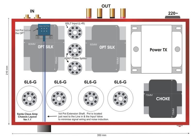 Changes: -Out goes the Novals; in come the Octals. -Put the power on/off switch. Now what you want? Hope not Samantha Fox-ji ?? [Beitrag von screamgigi am 17. Okt 2006, 12:42 bearbeitet] |
||
|
Manek
Inventar |
#17
erstellt: 17. Okt 2006, 17:10
|
|
|
Thats great Santa..... Ok...I see no source selector..maybe that could be a box external to the amp ? or internal to it ? Manek. |
||
|
Shahrukh
Inventar |
#18
erstellt: 17. Okt 2006, 17:33
|
|
Not needed na?!! There's only 1 set of line line-ins! Right screamin? |
||
|
screamgigi
Stammgast |
#19
erstellt: 17. Okt 2006, 18:26
|
|
|
The Input Selector has been designed out. Not that it can not be put back. This amp is being projected as a simple but highy quality build. I feel mostly we listen to one source. The input sensitivity is built around the assumtion that a CDP will be the primary source. Unless of very highly quality, an input selector only degrades the sound purity. We dont want too many contacts, solder joints etc in our signal line. Do let me know if that is a must. |
||
|
Manek
Inventar |
#20
erstellt: 18. Okt 2006, 07:08
|
|
|
yeah..agree ! BTW what would the sensitivity and input impedance of the line in sockets be like ? manek. |
||
|
screamgigi
Stammgast |
#21
erstellt: 18. Okt 2006, 09:12
|
|
|
These are some of the anticipatory specs. We shall measure once the build is complete: Input Sensitivity: Around 850mV for PO of approx 15 watts RMS at 8Ohm. Input Impendence: 100K Output Impendence: 8 Ohm (we have only that tap with the available Output Transformer. Output resistance: Less than .8 ohms. Freq Response: 15cps to 25Kcps at 10 watts RMS. (+/- .3dB) THD: Less than .1% at 1000cps upto full power For IMD and Phase Shifts etc we will need to really see how the SILK OPT perform in the circuit. As mentioned, these are specs we should be aiming for. A lot depends on the Transformer, which is an unknown quantity for us at the moment. Once the amp is made we shall test it for all parameters and to ensure that it remains stable under different load conditions. I am awaiting word from Viren-ji on the Power Transformer. |
||
|
screamgigi
Stammgast |
#22
erstellt: 18. Okt 2006, 09:31
|
|
|
Here is a slightly "square" layout. Footprint is a little less than the other version. 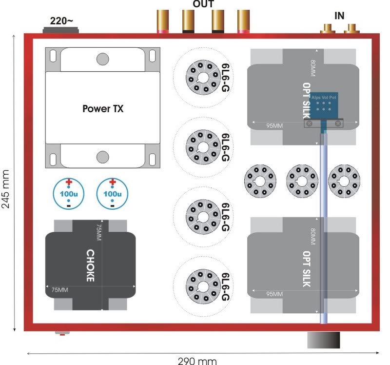 ...or are we loosing the plot here.. |
||
|
Manek
Inventar |
#23
erstellt: 18. Okt 2006, 10:25
|
|
|
I sonehow liked the earlier plot.....but would this orientation make any significant differences besides smaller footprint ? manek. |
||
|
screamgigi
Stammgast |
#24
erstellt: 19. Okt 2006, 06:49
|
|
|
None that I can think of, If you talking for an electrical point-of-view. Its equaly good or bad as the last one. Maybe this layout will call for a slightly longer run from the OPT to the Binding Post. I will post some classis and moder amp pics so that you can form an opinion. |
||
|
Krish
Stammgast |
#25
erstellt: 19. Okt 2006, 08:27
|
|
Gigiji, Yeh technical cheezen to mere palle nahin padta, lekin jo bhi ho, layout to zaroor sunder dhikh raha hai. Agar aap bambai se talukat rakhte ho, to hume ghar bulayega Hum is khoobsoorat cheez ko zaroor sun na chahege.  K |
||
|
Amp_Nut
Inventar |
#26
erstellt: 19. Okt 2006, 08:57
|
|
|
Just a thought..... Maybe a better idea to show off the tubes, ... sort of Front Row, rather than hide them between 2 X Formers ? Also position the Xformers so that they are Rt angled wrt each other to minimise cross coupling of their magnetic fields ? Cheers |
||
|
viren
Stammgast |
#27
erstellt: 19. Okt 2006, 11:30
|
|
|
Screamgigi, Finally some details on the power transformer and choke: Power Transformer, EI core Rs.1,700 (plus 12.5%+16.3% sales and excise taxes) Approx. size 100x115x100mm(depth) Choke, EI core Rs.750 (plus 12.5%+16.3% sales and excise taxes) Approx. size 90x75x75mm(depth) These are manufactured by Delta Transformers in Delhi. See www.deltatransformer.comViren. |
||
|
screamgigi
Stammgast |
#28
erstellt: 19. Okt 2006, 13:07
|
|
Mahashay, App tachniki maamle ki tanik bhi chinta naa kare. Hum ek vishwa-stariya dhawni uupkaran ka nirmaan kar rahe hain. Jub yeh dhwani vistarak yantra taiyaar ho jayega, aap ke saamne prasttut kiya jayega. App isse audition karne ka kast jaroor karein. Hum aapke aabhari rahenge. |
||
|
screamgigi
Stammgast |
#29
erstellt: 19. Okt 2006, 13:07
|
|
Amp-Nut-ji Yes. We will follow the first layout. You will note that OPTs are already oriented at 90deg to the PTX and the Choke. |
||
|
screamgigi
Stammgast |
#30
erstellt: 19. Okt 2006, 13:16
|
|
Viren-ji. Thanks. I have been using DELTA for last 25 years or so. I am attaching a scan of the DELTA Power Transformer brochure from the mid 70s. Models underlined in red are the ones I have used in past.  DELTA can still wind as per this old list. Unfortunately, as you will see none of the listed models meet our requirement. Is that a custom wind by DELTA you have procured? |
||
|
viren
Stammgast |
#31
erstellt: 19. Okt 2006, 19:30
|
|
|
Screamgigi, Delta even has old designs for push-pull output transformers - mostly PA stuff, not really suited for hifi. What I have been getting from them are all custom designs, including the power transformer and choke quoted for the 'Munna' amp (I like that name!). Viren. |
||
|
screamgigi
Stammgast |
#32
erstellt: 19. Okt 2006, 20:04
|
|
|
Viren-ji Yes DELTA makes some solid transformers, but if you read the rated specs carefully they are all positioned rather awkwardly. For instance if you want a transformer which can deliver 200mA for an EL84 Push Pull stereo, you will be looking at a voltage range of 370-ct-370. Way too high. Ideally you want 300-ct-300 but at that bracket DELTA offers a max current of 125mA. So you are neither here nor there. At best they are suitable for a Monoblock build. Another major drawback with DELTA is that their primary winding is quite high at 230volts. In most parts of India you will be lucky to get a steady 210 volts wall AC. Its a shame cause DELTA still makes reasonable transformers. I have been buying from the DELTA dealer in Kolkata who is close to 90 yrs old but still very alert. I have used DELTA PP OPTs for Guitar amps. Their SE OPT for EL84 is surprisingly good. Its only about Rs. 75 but audibly not much different then the US$ 100 Hammond! As a plus point it offers two separate secondary windings. If you want to experiments with Cathode feedback then its a good option to have. Uncharacteristically for this business segment, they are quite email friendly. I was discussing with them a pair of high voltage custom windings for my 845 SE amps. I had once enquired about sourcing wideband audio grade OPTs. They required a minimum production run of 20 pairs. But their custom design costs are very close to what I am quoted from my overseas winders. |
||
|
screamgigi
Stammgast |
#33
erstellt: 21. Okt 2006, 10:13
|
|
|
We are doing some major changes on the circuit and layout. Electrical: We are now going to use the excellent small signal pentode EF86 as our input device. This is a very high quality and expensive pentode specially developed for critical application such as Phono stage, preamps and input stages of high-end audio equipments. We will now clone the classic Eico HF22 amplifier circuit. We may wire the EF86 in triode mode to keep sensitivity and distortion even lower. We are still sticking with the SS rectification and Electrolytic PSU capacitors. Layout: We are now following the Japanese school of thought. Tubes upfront, iron at the back. Pos: -Slimline look. Tall and deep -Will occupy less frontage in the audio rack. -All the tubes in display -Power transformer and choke consigned to the back. -Less complicated; we now loose the Volume pot extender shaft and its assorted hardware. Aligning that Vol pot, extender shaft and the Vol Knob could be pain at times. Con: -Greater signal run. Now we need to properly shield and route the signal carrying wires from the back to the front where the Pot is located. This can be eliminated if the line input jacks are also located in the front. I do that times. Take you call on this. -We will also need to locate the power switch at the back. Now we will use an IEC socket that is switched and fused. Great under the circumstances. 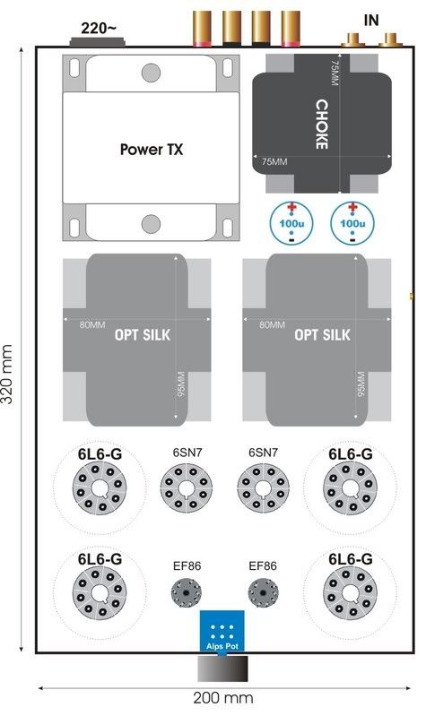 Do we make this change? Next week we start the actuall work on building the amp. [Beitrag von screamgigi am 21. Okt 2006, 10:18 bearbeitet] |
||
|
Manek
Inventar |
#34
erstellt: 21. Okt 2006, 11:29
|
|
|
what internal wiring will we use ? teflon coated would solve your shielding problems ? or would you need wiring with a briaded shield and teflon ? Any reason to change to the EF86 ? Manek. |
||
|
screamgigi
Stammgast |
#35
erstellt: 21. Okt 2006, 12:55
|
|
|
EF86 is inherently a better tube than the octal triodes like 6SL7 or 6SN7 for that position. Its a very linear driver from end to end. We are solving many problems that arise with a Triode in that place, namely Miller Capacitance. Of-course we loose that if we triode wire the EF86. Another advantage is that the high gain of a pentode can be used to apply lots of global NFB to get better damping. All things equalEF86 are sonically a solid tube. We will use 99.99% silver cable inside for hook-up [Beitrag von screamgigi am 21. Okt 2006, 12:56 bearbeitet] |
||
|
screamgigi
Stammgast |
#36
erstellt: 21. Okt 2006, 14:43
|
|
|
This is the orginal EICO Monoblocks that we gonna clone. Electrically of-cource. Not the layout.  |
||
|
screamgigi
Stammgast |
#37
erstellt: 21. Okt 2006, 14:46
|
|
|
Our build may look something like this 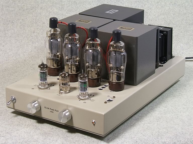 |
||
|
Manek
Inventar |
#38
erstellt: 21. Okt 2006, 15:04
|
|
|
The silver wire would be from your friendly neighbourhood jeweler I assume ? manek. |
||
|
screamgigi
Stammgast |
#39
erstellt: 21. Okt 2006, 17:55
|
|
Yes sir. That is the only reason my wife's jeweller doesnt not get clobbered by me. I am unusually considerate with him inspite of the crap he keeps peddling to her. We can consider the octal 6SJ7 in place of Noval EF86. That can bring back the "wow" factor though not necessarily best performance. BTW the folks this is the Divali night in my part of India. My daughter and wife are throwing an elaborate do. I wish you and your folks happiness and prosperity in these festive times |
||
|
Manek
Inventar |
#40
erstellt: 22. Okt 2006, 06:43
|
|
|
we leave the octal or noval judgement to you then. Viren, you have anything to add to whether the 6sj7 or EF86 for this design ? manek |
||
|
viren
Stammgast |
#41
erstellt: 23. Okt 2006, 06:52
|
|
|
Manek, Screamgigi, The choice is screamgigi's, since the design is his. Each valve has its merits - the design should be built around it. The EF86 has been used extensively in the classic amps - the QUAD II and the Mullard designs. If you intend to use feedback, you need a high gain input stage, that the EF86 can provide. If it were a choice of input triodes, however, I would pick the 6SN7/6SL7 anyday over the ECC82/ECC83. Viren. |
||
|
screamgigi
Stammgast |
#42
erstellt: 23. Okt 2006, 07:21
|
|
|
Actually the design is not mine Its been there since the dawn of time. Or more specifically when Mullard came out with the new world design tubes and its application circuits. We will only adapt it to our needs and OPT.EF86 One major reason for the switch over is that we will use the amp without a linestage. CDP will be plugged in directly to the input. The 100K pot will act as an attenuator. A high gm pentode will provide us with enough gain to drive the amp to full power. Of-course a triode like 6SL7 or ECC83 can provide enough gain. But the EF86 may do it better. So what happens if we decide to use a linestage. Simple. We will bypass the vol pot and plug in the linestage. If the result is unsatisfactory, e.i. too much gain or clipping, then we wire the EF86 in triode mode. That way we even reduce the parts count by loosing a resistor and a capacitor from the signal path. Our gain is reduced and so is distortion. So do we have a concurrence on the EF86 ? All: I am quite surprised that this initiative is not finding favour with more posters. Here we have a good opportunity to see how a tube performs and how an amp is built around that. I was always awestruck looking at forum members discuss tubes audio such fevershly in the other threads. I continue to be amazed by the learning here. I thought that when an actual opportunity presents itself, we will have a wide range of inputs and suggestions on building an amp from grounds up. Come to think of it, this is a good opportunity to shine light on some of the legends and hearsay that often accompanies tube audio We can even have an audition round of the amp when the build is done. So I am keen to have your feedback, wishes and demands on how we build this amp. [Beitrag von screamgigi am 23. Okt 2006, 09:01 bearbeitet] |
||
|
stevieboy
Stammgast |
#43
erstellt: 23. Okt 2006, 12:04
|
|
|
that's about all the contribution i can make screamgigi. all you're saying is going way way above my head. though i get the general drift... if i could presume to ask you post a slightly dumbed down version of the basics of a valve amp from how the signal enters it, what the capacitors, resistors, transformers, attenuators, pots do, till the signal is sent out, i'd be most grateful. then a lot of what you're posting and the choices you're making would make sense to me. and now i go hide in embarassment having displayed my prodigious ignorance. [Beitrag von stevieboy am 23. Okt 2006, 12:08 bearbeitet] |
||
|
Manek
Inventar |
#44
erstellt: 23. Okt 2006, 12:26
|
|
|
screamgigi... stevie has a valid point....a small post would do nicely. manek. |
||
|
Amp_Nut
Inventar |
#45
erstellt: 23. Okt 2006, 12:54
|
|
|
screamgigi said :
I know that Manek has his heart set on the 6SN7. Using the EF86 will break his heart.... Do reconsider - for Manek's sake From my side, I AM following your posts, and enjoying it. Only a 20 Watt conventional Valve amp does not float my boat, though it looks like its turning out very nice ! Keep up the good posts. Cheers |
||
|
Manek
Inventar |
#46
erstellt: 23. Okt 2006, 13:27
|
|
|
Amp_nut....yes, I do love the 6SN7 tubes I have heard the quad II as well and have loved that sound so its not that bad a heartache. Go with whatever you think is right screamgigi. Any chance of beefing up that 20W ? Do consider - for Amp_nut's sake regards, manek |
||
|
stevieboy
Stammgast |
#47
erstellt: 23. Okt 2006, 13:52
|
|
|
or maybe go lower, just cut out the 0 and do a 2 watter SET nothing like it is available here in india except wavac which is way out of reach. |
||
|
screamgigi
Stammgast |
#48
erstellt: 23. Okt 2006, 15:16
|
|
|
stevieboy-ji Yes you do have a very valid point. Only if I knew what each component does in the circuit I just follow the schematic. If a dimwit like me can understand and build tube audio, so can you and your cat.Reproduction of audio with tubes is a relatively simple affair. If you are talking about amplifier than you have Single End (SE), Push Pull (PP) or Output Transformer Less (OTL). Most commercial and DIY amps are either SE or PP incorporating some variation. OTLs are something else. Although the process is quite simple, putting the funda in one post can get a little dense. So if you allow we can follow a practical approach and keep the gyan to minimum. We shall keep adding as we go along. An excellent online primer can be found at Tubes for Newbies - Bonavolta homepage. Then here you have the learning section at the Diyaudio.com. Check out both of them. It cant get any better than that. Here we will first put a schematic and then discuss it. I believe many folks like Amp_Nut-ji, sivat-ji, Manek-ji and of-cource Viren-ji here possess quite deep understanding of tubes and how they work. But for many of us I hope this thread becomes a start point for that wonder journey into tube audio. We will discuss how each tubes works, its role and why it is chosen. We shall post pictures of the tubes and their data sheets to explain how the operating conditions are chosen and what would happen if another tube were used instead. We shall discus each component, why that particular value and flavour was chosen and how it will contribute to its selected place in the amp. Yes we will also discuss the wires; thank you This will be an unpretentious, solidly engineered and well-built amp. We hope to document the building so that one interested in nitty-gritty can dig into it. We shall keep the Indian DIY context in mind while doing that. Finally, once the amp is built we shall test it for all parameter. Speakers are torturous load. To ensure that our little Munna is always stable, we shall test it under purely resistive/capacitive and complex loads. My usual test regime is very strenuous. I doubt even some of the commercial amp makers would be doing that. Its far too complex and time consuming for everyday situation, but we shall do that nonetheless. If our amp fails any of the tests, we shall not resort to shortcuts. We shall go back to design stage and find a solution while documenting the issue. We want an amp that can be handed down as a family heirloom. Once our amp clears all tests, we shall do critical listening tests. We will use varied source material. This is the time when we pursue that wonderful nerdy activity called tube rolling by trying out different tubes. We will learn to characterise a particular tube as dark, tight, fat or shy This is the most subjective part of the journey and I hope to find a way to somehow do it collectively. If this turns out well then in future we may proceed to building more projects such as Preamps, active crossovers etc in similar fashion. Amp_Nut-ji Manek-ji ka dil is smitten with 8 hole beauties. But here I am giving an extra one. With nine of em he aint gonna run of holes in a hurry But seriously, we can explore the 6SJ7. Its an Octal (8 pin) tube quite close to EF86 in performance. And of-course we can get back to 6SL7 for the input hole if needed. Manek-ji Theoretically we can run the tubes proposed here to pump out almost 50 WPC. But then it wont be hi-fi anymore. To maintain quality at higher output level we need different tubes and iron. It changes the equation completely. You are now looking at expensive ironware, capacitors and big tubes. And frankly, IMHO, tubes magic is best served in small quantity. If I really needed big watts I would move over to Solid State. I would rather back off on the power and aim for that golden watt as desired by stevieboy-ji. [Beitrag von screamgigi am 23. Okt 2006, 15:26 bearbeitet] |
||
|
Manek
Inventar |
#49
erstellt: 23. Okt 2006, 16:05
|
|
|
I agree on the power..... and would not mind the ninth hole as well Manek. |
||
|
viren
Stammgast |
#50
erstellt: 23. Okt 2006, 17:32
|
|
|
screamgigi-ji, You are superb! Please do carry on with your explanations. Viren. |
||
|
Amp_Nut
Inventar |
#51
erstellt: 23. Okt 2006, 18:54
|
|
|
screamgigi-ji, You are VERY VERY modest. With yr knowledge and hands on experience, you are amp-KING ! |
||
| ||

|
|
||||
| Das könnte Dich auch interessieren: |
|
DIY Headphone amp Manek am 20.09.2006 – Letzte Antwort am 21.09.2006 – 25 Beiträge |
|
My second DIY tube amp .The starving student Millet Hybrid Savyasaachi am 11.03.2009 – Letzte Antwort am 18.03.2009 – 13 Beiträge |
|
DIY Sub . sivat am 18.09.2008 – Letzte Antwort am 30.10.2008 – 24 Beiträge |
|
More tube projects on the starting block Savyasaachi am 24.03.2009 – Letzte Antwort am 11.03.2010 – 31 Beiträge |
|
DIY. Simple Back Loaded Horn project with vintage BOLTON drivers aks07 am 12.10.2008 – Letzte Antwort am 24.12.2008 – 27 Beiträge |
|
First tube amp.help a rookie? Savyasaachi am 27.02.2009 – Letzte Antwort am 23.03.2009 – 36 Beiträge |
|
DIY SUB India (Bangalore) cmsajith am 03.08.2009 – Letzte Antwort am 04.08.2009 – 6 Beiträge |
|
DIY Projector sivat am 20.09.2006 – Letzte Antwort am 22.09.2006 – 3 Beiträge |
|
DIY 300B DHT SE Amplifier Project aks07 am 14.01.2009 – Letzte Antwort am 22.02.2009 – 84 Beiträge |
|
My new DIY headphones Savyasaachi am 25.01.2009 – Letzte Antwort am 15.05.2011 – 6 Beiträge |
Anzeige
Produkte in diesem Thread


")


Aktuelle Aktion


Partner


Top 10 Threads der letzten 7 Tage
- Hotel Modus deaktivieren
- "diese anwendung wird jetzt neu gestartet um mehr speicherplatz verfügbar zu machen"
- Von HD+ zurück zu Standard-TV
- Remotekabel anschließen, aber wie und wo?
- Hisense verbindet sich nicht mehr mit dem WLAN
- Audiodeskription ausschalten (in ZDF App) 803er
- Umschalten von TV auf Radio
- Satellitenschüssel was und wie einstellen am TV
- Pro 7 und Sat 1 auf einmal weg.
- Markierung an Lautsprecherkabel - welche Norm?
Top 10 Threads der letzten 50 Tage
- Hotel Modus deaktivieren
- "diese anwendung wird jetzt neu gestartet um mehr speicherplatz verfügbar zu machen"
- Von HD+ zurück zu Standard-TV
- Remotekabel anschließen, aber wie und wo?
- Hisense verbindet sich nicht mehr mit dem WLAN
- Audiodeskription ausschalten (in ZDF App) 803er
- Umschalten von TV auf Radio
- Satellitenschüssel was und wie einstellen am TV
- Pro 7 und Sat 1 auf einmal weg.
- Markierung an Lautsprecherkabel - welche Norm?
Top 10 Suchanfragen
Forumsstatistik
- Registrierte Mitglieder931.134 ( Heute: 4 )
- Neuestes MitgliedOrren3g
- Gesamtzahl an Themen1.564.802
- Gesamtzahl an Beiträgen21.867.394
