| HIFI-FORUM » Reparatur & Wartung » Hifi-Klassiker » Grundig R3000 | |
|
|
||||
Grundig R3000+A -A |
||
| Autor |
| |
|
Antonello9796
Neuling |
#1
erstellt: 17. Jan 2019, 20:38

|
|
|
Hallo an alle und danke, dass Ihr mich ins Forum gebracht habt mein name ist antonello und ich lebe in sardinien das ist mein erster post Entschuldigung für die Fehler, aber ich verwende den Google-Übersetzer also ... sie gaben mir eine grundig 3000 und einen empfänger Leider war es tot und ich habe es repariert liste die reparatur auf Ich habe die Sicherung auf der Primärseite verbrannt Also zog ich alle Steckdosen aus und versuchte den Transformator zu leeren. Ich tausche die Sicherung aus und brennt, sodass ich davon ausgehe, dass der Transformator kurz ist Ich suche einen anderen 3000er für Ersatzteile, ich finde einen und beschädigt, aber der Transformator ist in Ordnung, also ersetze ich ihn Jetzt schaltet sich mein 3000 ein, aber kein Relais ist aktiviert Ich überprüfe die letzte Phase und finde, dass der richtige Kanal kurz ist, um das von 3000 gesammelte Finale für Ersatzteile zu ersetzen Ich schalte den Strom im Ruhezustand bei 30 mv ein und die Relais klicken und spielen jetzt Es gibt jedoch ein weiteres Problem, dass der rechte Kanal nur den linken Kanal stummschaltet Überprüfen Sie die letzte Etappe und in Ordnung Das Signal reicht bis zum Lautstärkepotentiometer, es wird jedoch nur ein Kanal ausgegeben Nach einigen Versuchen stelle ich den rechten Kanal auf den linken Kanal und jetzt funktionieren beide aber das audio ist nicht stereo und mono wo bin ich falsch ??? Ich akzeptiere jeden Rat danke |
||
|
oldiefan1
Inventar |
#2
erstellt: 18. Jan 2019, 06:09
|
|
|
Hello Antonello9796, Welcome to the HiFi-Forum! Because I notice that the Google translator doesn't do a good job, I am answering in English. I hope, That you can manage in English. if not, Google translator won't have more difficulties with English-Italian than with German-Italian. First let me summarize what I understood from you. Please correct me, if there is something wrong in my understanding. Through the google translation some contradictions appear in your text. We must clarify that first. 1. Your Grundig R 3000 stereo-receiver (amplifier-tuner, amplituner) blew the mains fuse (primary fuse) Si1 (2A, slow). 2. You replaced the transformer and the fuse didn't blow anymore 3. Later you found that the right channel has a short. Speaker protection relays of both channels remained open 4. You replaced parts in the right channel. Afterwards the speaker protection relays closed normally. 5. You can measure (between the points X and Y of both channels each) the correct idle current (measure 30mV, both channels) 6. Now you have the problem, that the right channel is muting only the left channel ("Es gibt jedoch ein weiteres Problem, dass der rechte Kanal nur den linken Kanal stummschaltet") 7. You can detect the audio signal through the pre-amplifier to the volume potentiometer in both channels. But get audio signal at the speaker outputs in one channel only 8. If you route the signal from the left channel to the right channel you have audio signal at both speaker outputs, but (of course) no stereo. A. It is very very very unlikely that the transformer was blown. Never ever anyone saw that with this mighty transformer, provided the correct fuse rating was in place (2A). Unfortunately, you had started from the wrong edge. A blown mains fuse does normally not indicate that the transformer is defective, it only means that there is a defect somewhere in the receiver, probably power supply or power amp, that causes a high current to be delivered by the transformer. An experienced person would have measured first the C-E (collector-emitter) resistance of the power transistors in the power amp channels first (if shorted or partially shorted in about 70-80% causes a main fuse failure) and secondly assured that there is no short in the large power amp filter caps and/or the power amp rectifier which in 10-20% causes the fuse failure. The transformer would be the very last culprit, practically never happens to become defect and most likely also not in your receiver. B. You might have had initially a blown power transistor in the right channel power amplifier section. In such case, if the collector-emitter path of a power transistor gets shorted, a very high current is drawn from the power supply and the primary fuse for the transformer may open. Also the large high-power emitter resistor can open (become high) under such condition. In the repair care must be taken that not only the defective power transistor is replaced but also its complementary one (there are two power transistors per channel in the R3000). Further, ALL semiconductors (all transistors and diodes) of the broken power amp channel must be checked carefully and the resistors investigated for signs of burning or discoloration, in the latter case to be replaced. At this time, it is recommended to also replace the electrolytic capacitors in the power amp, except the two large ones which only need to be replaced if found defective or if one lost its rubber plug on the top. After defective parts are all relaced and all parts are found ok, the receiver shall be connected to 230V mains voltage via a 60W incandescent light bulb in series - not LED lamp, not fluorescence lamp or other; it must be an incandescent lamp! Pay attention that this lamp connection is electrically safe, that no 230V parts can be touched or remain open, 230V is lethal!). No speakers shall be connected. The lamp limits the current through the receiver when switched on, in case that there are still defects. When switching on the receiver, the lamp would initially light up (higher current when charging the large capacitors) and then become dimmed as the idle current of the receiver is low, if everything is ok. If however, the lamp keeps lighting bright, there is still a serious defect in the amplifier causing high current. C. Alternatively, if the initial defect was not caused by a blown power transistor, opening of the primary (mains) fuse of the transformer can also result if either one of the big power diodes on the power supply board (attached to the transformator) had become shorted (this is quite unlikely, though). Much more likely is an internal short inside of one of the big two electrolytic capacitors (the two aluminium cans) at the right side of the transformer. I have seen these capacitors often failed nowadays, in some cases with internal short but not in all. In case of such capacitor defect, it is sufficient to replace both large capacitors and the mains fuse. Usually there are no secondary defects caused. In your case however, as the receiver status is described, you definitively have defects in at least one power amp causing the speaker relays to open. D. Please tell, which root cause you found/assumed for the initial defect, any of the outlined or a different one? E. Please list the parts (by part number in the R3000 schematics) you have replaced so far F. Please clarify the following: You wrote: "Ich schalte den Strom im Ruhezustand bei 30 mv ein und die Relais klicken und spielen jetzt" "Es gibt jedoch ein weiteres Problem, dass der rechte Kanal nur den linken Kanal stummschaltet" In my English translation as I understood: 4. You replaced parts in the right channel. Afterwards the speaker protection relays closed normally. 5. You can measure (between the points X and Y of both channels each) the correct idle current (measure 30mV, both channels) 6. Now you have the problem, that the right channel is muting only the left channel. Something got srewed up in the translation? Can you please circumscribe again with other words what you observe? Either the speaker relays work now correctly and click and close - correctly would mean both relays, for both channels. Or they don't. It is normally not possible that only one of the two speaker relays switches while the other doesn't, except if one of the two relays is defective. Possible relay defect: contacts got welded together because too high current had occored before so that they can't open anymore; or in the other case, relay coil became open so that the defective relay can't pull the contacts together. By principle, if there is DC of >100mV (or so) on either the right channel power amp section output or the left one, the protection becomes activated and both speaker relays open to interrupt the speaker output connections. In that case the DC on the output of the defective power amp stage cannot be detected on the speaker terminals, because the relay action. Measured must be done on the output lines before going into the relays. And always both relays either open and close simultaneously. If not, one of the relays is broken. It seems from what you wrote, that one of the two channels is working correctly, but not the other? How do you know that? Which channel do you assume to work correctly, left or right? Why do you think one is working fine and the other is not, what observations? Here is my conclusion (assuming I understood you right): If I assume that the left channel would work correctly up to its corresponding speaker relay and the right channel would be defective. And further assuming that the right channel defect would cause a DC voltage on the right channel power amp output. Then that DC must activate the speaker protection and both relays shall open in that case. If the relay in the output line of the defective right channel power amp does not open, its contacts must stick together (welded?) because of a defect of the right channel relay. --> replace the relay (you won't find this relay anymore, you need to build a litter adapter board to be used with one of today's available relays because today solder pin layout is different, not difficult, I can help you). IS THIS A CORRECT DESCRIPTION OF WHAT YOU WROTE? IF YES, CAUTION! You probably have then DC from the right defective channel on your right speaker output. This DC can damage your speaker (bass speaker coil may become grilled), if you attach a speaker. Never ever attach a speaker unless all defects are fully cured. If my above description is correct.... You wrote "Nach einigen Versuchen stelle ich den rechten Kanal auf den linken Kanal und jetzt funktionieren beide" If you route the signal from the left channel to the right channel you have audio signal at both speaker outputs, but (of course) no stereo. Question: Where and how exactly did you connect the signal to the other channel? If you did this re-routing behind the speaker relay, did you connect the left speaker terminal with the output of the right defective channel? In that case, you have both terminals attached to the defective right channel and have DC now on both outputs (may kill your speakers, if you would attach them). Furthermore, if you attach 4 Ohm (impedance) speakers you may further destroy the right power amp, because only a minimum of 4 Ohm per channel is allowed. With both outputs attached to the same channel in parallel, the resulting speaker impedance is 2 ohms only (4 Ohms in parallel to another 4 Ohms makes a total of 2 Ohms resistance). Hence you have set up the receiver now to self-destroy itself further and also kill loudspeakers, if you attach any. Enough for a first start. Please check carefully and respond. What did I get right, what wrong? Try to answer my questions as detailed a possible. Your receiver appears pretty much tortured by inadequate trials to fix it the wrong way. But we can cure that. Then in the next step, we'll move ahead with diagnosis and locating the defect(s). I hope English works for you? Google translator will have a problem with the technical language here, it's more suited to order a coffee. Best regards, Reinhard [Beitrag von oldiefan1 am 18. Jan 2019, 07:09 bearbeitet] |
||
|
|
||
|
Antonello9796
Neuling |
#3
erstellt: 18. Jan 2019, 16:22
|
|
|
Hello Reinhard surely google has badly translated some things anyway thanks for answering me more or less you understood my problem but I'll explain it better 1 the grundig burned the transformer fuse I disconnected from the whole circuit the transformer I put a new fuse and burned the same so I changed the transformer and the fuse does not burn anymore 2 I reassembled the transformer on the circuit I turned on the grundig but remained in protection so I checked the final stage and the right channel had the pair of shorted finals I replaced them and the final stage works well both channels with 30 mv current dict at that point I connect the speakers but it only plays the left channel the right and dumb and also in headphones and dumb 3 in the card where the potentiometer is welded there are two points of mass one for the left and one for the right I the right channel put it to ground on the left channel now you hear both channels but in mono 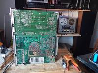 |
||
|
DB
Inventar |
#4
erstellt: 18. Jan 2019, 18:16
|
|
|
oldiefan1
Inventar |
#5
erstellt: 18. Jan 2019, 19:16
|
|
|
Hello Antonello9796, The picture tells me that we are talking the model R 3000-3, the very late version of the R 3000. OK, now I understand...seems a very rare case where really the transformer got an internal short. Anyway, now there is no transformer issue anymore. You write that the power amp now works well with 30mV (idle current measurement X/Y) on both channels. Then you write also that only the left channel plays and there is no output signal at the right channel. But both statements contradict each other. But now I understood that you could bridge the audio signal at the volume potentiometer and then you have output at the speaker terminals of both channels. That indicates that you lose the right channel signal BEFORE THE VOLUME POTENTIOMETER and all the remaining right channel up to its speaker terminal is fine, indeed. Hence, the problem is in the right channel preamplifier. The following applies, if I understood you right: There is a standard fault in the R2000 and R3000 -1 and -2 receiver series which kills the audio in one or both channels, namely shorts in certain tantalum capacitors in the preamplifier section. The R-3000-3 has been modified in the corresponding section but it is likely that a failed tantalum capacitor is also the culprit here. At least it is much easier to replace those capacitors in the R3000-3 than in the earlier receiver versions. 1. Please remove the bridge you attached at the volume potentiometer to distribute the audio signal to both channels from there. Your channels shall be completely separated again. 2. Feed an audio signal to the MONITOR input (right and left channel). Switch the MONITOR Switch at the front to MONITOR-ON. Do you hear audio (via headphone) now on both channels (stereo)? If you do hear both channels in case you feed the signal into the MONITOR input jacks with MONITOR switch ON, the defect is in the separate preamplifier for the other inputs. MONITOR has its own preamplifier so that the MONITOR input remains unaffected. Measure DC against chassis ground at measurement points RG and LG, both shall be about 31 V DC. LG value should show this value approximately, because left channel is ok. If RG deviates significantly (i.e. much higher), replace tantalum capacitors C614 (10µ/50V) and C625 (10µF/50V). You may use aluminium electrolyte capacitors here instead, because experience shows that tantalum capacitors tends to fail in these positions frequently. To be on the safe side, you may want to replace the corresponding tantals in the left channel (C613 and C624) also, because they may fail also sooner or later. If you don't hear the right channel, but only the left, even if the audio signal is fed into the MONITOR left and right input jacks, it becomes more tricky. Let's see what you find. Here the location of the measurement points RG and LG. The mentioned capacitors should be close to it. 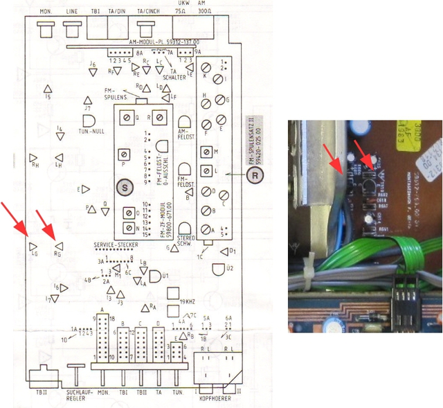 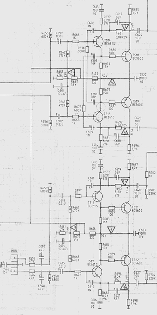 Addendum You wrote.... "...in the card where the potentiometer is welded there are two points of mass one for the left and one for the right I the right channel put it to ground on the left channel."[/i] It is not correct, I believe. There is only one common mass for left and right channel. Your white wire does not connect left and right ground (mass). It connects left and right signal paths at the capacitors C801 and C901. - Just for those readers who got confused by this screwed-up sentence (blame the machine translator!). Can you please put here a close-up photograph of the board (solder side)where the volume board goes into the main board and where your white wire is attached? Then we can see what is connected by the wire. 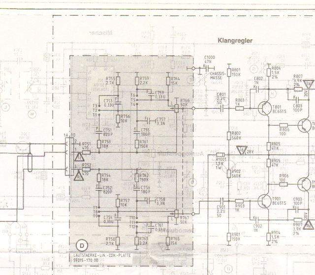 Best regards, Reinhard [Beitrag von oldiefan1 am 19. Jan 2019, 01:24 bearbeitet] |
||
|
oldiefan1
Inventar |
#6
erstellt: 26. Jan 2019, 21:59
|
|
|
Any progress? Regards Reinhard |
||
|
Antonello9796
Neuling |
#7
erstellt: 27. Jan 2019, 19:27
|
|
|
Forgive me for the absence but I'm not well I had to put aside the grundig as soon as I'm better I take it back and do the checks you suggested thank you sorry again I hope next week to get better |
||
|
oldiefan1
Inventar |
#8
erstellt: 28. Jan 2019, 16:19
|
|
|
Take care of yourself! The Grundig can wait. Wish you all the best, Reinhard |
||
| ||

|
|
||||
| Das könnte Dich auch interessieren: |
|
Grundig SV200 Reparatur, .315a Sicherung durchgebrannt fede65r am 23.09.2020 – Letzte Antwort am 27.09.2020 – 9 Beiträge |
|
GRUNDIG C 9000 Reparatur - Sicherung brennt durch sirene am 27.01.2008 – Letzte Antwort am 09.06.2008 – 5 Beiträge |
|
Grundig R3000 Fehler Valvotek am 21.08.2022 – Letzte Antwort am 25.08.2022 – 10 Beiträge |
|
Grundig C9000 Sicherung brennt durch Pello120 am 03.01.2013 – Letzte Antwort am 05.01.2013 – 3 Beiträge |
|
Grundig RPC 320 Sicherung brennt durch digger955 am 18.06.2016 – Letzte Antwort am 20.06.2016 – 6 Beiträge |
|
Grundig R3000 brummt links Herr_Latz am 16.11.2008 – Letzte Antwort am 12.02.2009 – 11 Beiträge |
|
Grundig T 3000 bleibt tot nach Reparaturversuch cabrio am 21.06.2006 – Letzte Antwort am 02.09.2018 – 4 Beiträge |
|
Grundig Stereomeister 3000 UKW tot ! cabrio am 15.09.2007 – Letzte Antwort am 15.09.2007 – 5 Beiträge |
|
Grundig R25 Sicherung und Problem! Tenmat am 25.08.2010 – Letzte Antwort am 26.08.2010 – 4 Beiträge |
|
Grundig R 3000-2 abgeschossen! Daniel_Schwenk am 21.03.2015 – Letzte Antwort am 24.08.2018 – 10 Beiträge |
Foren Archiv
2019
Anzeige
Produkte in diesem Thread


Aktuelle Aktion


Partner


Top 10 Threads in Hifi-Klassiker der letzten 7 Tage
- Kondensator ersetzen mit höherem Wert - zulässig?
- WD40 als Kontaktspray?
- Grundig R-2000 Mutingproblem
- Entstörkondensator- Beschriftung und deren Bedeutung
- Dreh - Lautstärkeregler defekt? reagiert falsch oder gar nicht Aiwa NSX AV 320
- Problem bei Reparatur von Pioneer CT 676
- Marantz / Superscope CD-302A Tape Deck
- "Tapedeck-Reparatur" Thread
- Welche Glassicherungen/Feinsicherungen Flink oder Träge ?
- Akai GX-260D-Überholung, Transistorersatztypen?
Top 10 Threads in Hifi-Klassiker der letzten 50 Tage
- Kondensator ersetzen mit höherem Wert - zulässig?
- WD40 als Kontaktspray?
- Grundig R-2000 Mutingproblem
- Entstörkondensator- Beschriftung und deren Bedeutung
- Dreh - Lautstärkeregler defekt? reagiert falsch oder gar nicht Aiwa NSX AV 320
- Problem bei Reparatur von Pioneer CT 676
- Marantz / Superscope CD-302A Tape Deck
- "Tapedeck-Reparatur" Thread
- Welche Glassicherungen/Feinsicherungen Flink oder Träge ?
- Akai GX-260D-Überholung, Transistorersatztypen?
Top 10 Suchanfragen
Forumsstatistik
- Registrierte Mitglieder931.200 ( Heute: 2 )
- Neuestes Mitgliedtougui63
- Gesamtzahl an Themen1.564.943
- Gesamtzahl an Beiträgen21.872.887
