| HIFI-FORUM » Reparatur & Wartung » Hifi-Klassiker » Revision eine Sanyo Plus P-55 Endstufe | |
Gehe zu Seite: |vorherige| Erste Letzte
|
|
||||
Revision eine Sanyo Plus P-55 Endstufe+A -A |
|||||
| Autor |
| ||||
|
Poetry2me
Inventar |
#51
erstellt: 25. Sep 2021, 01:51

|
||||
|
@csari0: I am away from home this Weekend, Sorry. Will give you transistor types you can use as replacement beginning of next week. - Johannes |
|||||
|
Poetry2me
Inventar |
#52
erstellt: 26. Sep 2021, 20:44
|
||||
|
Replacement transistors which have proven to work in multiple successful restorations of Sanyo Plus P55 power amplifiers. These transistors match or exceed the relevant parameters of original types and will work in the respective positions (also for many other power amplifiers). TO92 format (small signal type): PNP: 2SA992 NPN: 2SC1845 TO126 or TO92L/large format: PNP: 2SA1381 or KSA1381 NPN: 2SC3503 or KSC3503 Linear regulation of supply rails for the VAS (voltage amplification stages) of Sanyo Plus P55: In one of the P55 I found a problem in the power supply linear regulator. It would let through full rectified voltage of >70V instead of regulating to 56V. The amp would still work ... somehow, but was having occasional crackle noise events due to transistors within the amp circuit breaking through. Inspecting the darlingtons showed that both original NPN (positive rail 56V) and PNP (negative rail) seemed to be originals but were wrong 60V types and needed replacement with 80V or better 100V types. I used MJF122 and MJF127 which worked fine. I hope this helps. - Johannes [Beitrag von Poetry2me am 26. Sep 2021, 21:36 bearbeitet] |
|||||
|
|
|||||
|
csari0
Neuling |
#53
erstellt: 27. Sep 2021, 03:45
|
||||
|
Thanks John, this information helps a lot . I wasn't aware FETs could be an issue. Thanks for that one too, I'll look into MJF122/MJF127 After you suggestion I did a search and found that some people use MJE350/MJE340 to replace the 2SK150. I have not done enough research to see if it's true. I have a few MJE350 at hand, so hopefully it's true... I'll do a little more digging. (OnSemi websites states the MJF122/127 are similar to the TIP122/127) As for the SD755,I found SK3931 would work for the SD755, but hard to get... so thanks for the SC3503 tip. I had checked the KSC1845, seems those little fellas are the cure for many ails along with the A992s. The one concern I had was the MHz... the C1845 has 50MHs, and the D755 has 350Mhz. At least the C3503 has 150MHz... but to be honest I'm not sure Hz are a big issue, I jut know there is a big gap between 350 and 50. From my research, I found that SC3503 can also replace the SD668a, which in my unit they have black feet. In regards to the O.P, and his information and pictures. I have figured out what value the Wimas on the boards are. I'm glad that is sorted out. Only issue is finding a 47pf Wima that is not 1kv. As for the resistors, I'm not sure if I have it right with the resistors. He seems to have replaced two 5.6ohm resistors with 2.2ohm (R911,R912). I'm not sure if I got the values correct, hard to tell whether it is red or brown with those bands. By the size I would say they are most likely 2w. Also I notices O.P put a 15pf/500v mica to replace the 15pf/500v ceramic cap. Any reason why he didn't replace the 10pf/500v ceramic with a mica too? At the moment I'm waiting for a shipment of KSC1845/KSA992 to finish the C55. The list for the P55 is getting long, and pricey considering I'm buying parts for two P55s, so when I get the second one, I don't have to wait around for parts. No big rush, seems all sellers have sold out of the CDE power caps, earliest arrival is in late November. Once again, thank you John. Regards, Csari0 |
|||||
|
Poetry2me
Inventar |
#54
erstellt: 27. Sep 2021, 10:46
|
||||
|
MOSFETs vs. Darlingtons: Wait, I was not relating to the MOSFETs at all ! MJF122/MJF127 are regular bipolar Dralingtons and I used them to replace Q911 and Q912. PCB-Problems We never replaced any of the original MOSFETs as these still work fine. Only, you will notice fluctuating idle current due to bad solder joints of the 2x0.47 Ohm source resistors. Simple re-soldering or exchanging these resistors will not helb sustainably. Therefore, what you will have to do: Dismantle the two small PCBs holding the TO3 MOSFET sockets and source resistors (PCB for the current amp stage if you will). Remove all parts and all old solder and clean the PCB from any residues of flux !!! Unfortunately these PCBs have taken up some very bad flux plus some water as well it seems (Pertinax is hygroscopic). We tried and tried by resolderinng, using fresh solder etc. It never worked. If you do not clean these two small PCBs, you will never have a stable and equal distribution of idle current between the two parallel MOSFETs. Which transistors need to be exchanged? Whenever I came across blackened pins of transistors, I ignored it. It could be caused by chemical reactions (oxidization) rather than thermal reasons (?). Not completely sure. Therefore, at least for a first throw, I would only exchange the TO126 case transistors of the third differential stage (Q706..710, Q806..810) as these suffered extreme thermal stress. In the course of the years we found several problems around these transistors (from crackle noise to oscillation to full exitus). Maybe you will want to exchange the second stage as well (Q703, 704, Q803, 804) using KSA992/KSC1845 as this stage runs at only 1mA idle current and will require below 20mW per transistor. For a start, I would leave all other transistors in place. Regarding the 15pF capacitors: We generally try to replace ceramics as we mistrust them (multiple reasons). We use MKP where we can obtain the values (ususally down to 33pF). We use mica for values below the MKP range. Sometimes we did not find any or parts are running out. Wima capacitors: Careful when relating to MKS series. There is a MKS2 series (5mm only pinout) and then there is MKS02 (2.5mm only pinout). Resistors R911 and R912: 5.6 Ohms are correct. These resistors are intended to "burn down" some of the voltage and also act as protection. Do not forget to add one film capacitor (low single digit µF capacity) to ground between the resistor and respective darlington transistor. This will give you sonic improvements. - Johannes [Beitrag von Poetry2me am 27. Sep 2021, 10:50 bearbeitet] |
|||||
|
Valenzband
Inventar |
#55
erstellt: 27. Sep 2021, 12:04
|
||||
Don't worry. Both datasheets state "typical values" and "minimum values" at different currents. However, ft depends on current anyhow. The more detailed graphs show quite similar behavior accross Ic. In this application they operate near 1mA where ft should be above 100MHz for both types. Other parameter to look at are similar as well.
Blackening of pins appears on many components over time. Both oxygen or sulfur can react with constituents of the alloy used for pin pre-solder. It is similar but not the same as blackend silver, encountered on many contacts. Sulfurized lead or tin is very hard to remove by flux at useful temperatures. Well, at least those flux agents which do not destroy the rest of the circuit ... Wih respect to components, i.e. transistors, it is hard to tell whether they are at risk to fail due to progression of wire and bond corrosion within the epoxy. Epoxy mold is not well suited for full protection over periods of several decades. There is no such thing as TO92 in any space craft. [Beitrag von Valenzband am 27. Sep 2021, 13:13 bearbeitet] |
|||||
|
csari0
Neuling |
#56
erstellt: 28. Sep 2021, 04:12
|
||||
OK, I wasn't planning on playing with the mosfets, but thanks for clearing it up for me. I got the transistors in my basket.
I cleaned the boards already,they were very filthy, just like the driver boards, Sanyo must have extra stock of the flux spray to make the electronics smell when they are ne and you plug them in... they used a lot! I haven't dismantled it yet. Once I install the capacitors and resistors, I will give it another clean.
Ok, good to know, thanks
So the original value is 5.6, but the O.P put 2.2. I should go with 5.6?
Single digit? The O.P mentioned 3.3 uf "shunts" are those the ones you are referring to? Thanks John, you have been very helpful. [Beitrag von csari0 am 28. Sep 2021, 04:22 bearbeitet] |
|||||
|
csari0
Neuling |
#57
erstellt: 28. Sep 2021, 04:30
|
||||
So you are saying that it would be OK to replace the 2SA1085/2SC2545 with KSA992/KSC1845. If that is your suggestion, that would make it easier since I have a bunch of 1845/992 on the way.
Well, I don't always plan on changing all transistors, but I know considering the age, I would be avoiding a future issue by replacing them now, since the unit is apart, and I have instant access to the boards. So I will change as many transistors as I can, as long as I can get the proper replacements. Thank you. [Beitrag von csari0 am 28. Sep 2021, 04:46 bearbeitet] |
|||||
|
Poetry2me
Inventar |
#58
erstellt: 28. Sep 2021, 08:28
|
||||
|
R911 / R912: We have used 2.2 Ohm at times but later returned to the original value of 5.6 Ohm, as stated in the schematic. And yes: For the extra capacity behind it we used 3.3µF. see Post #9Replacement transistor recommendations for small signal types remains as stated above and obviously repeated by others: KSA992/KSC1845 These are even capable of managing 100mW instead of 50mW as with most of the small signal types. All other parameters match or exceed the other types used, including very low noise figures and very high max voltages. Just make sure to buy these through reliable channels, which should not be ebay or Alibaba. Reliable production sources (K-Types used to be Fairchild, american made or at least quality-controlled) also gives you very low variation in parameters these days, provided they are from the same lot. Almost like you had selected them. PCB-Problems: Make sure to completely remove old solder as well, especially for the solder joints of the 0.47 Ohm source resistors. - Johannes [Beitrag von Poetry2me am 28. Sep 2021, 16:02 bearbeitet] |
|||||
|
Valenzband
Inventar |
#59
erstellt: 28. Sep 2021, 11:10
|
||||
Where do 2SA1085/2SC2545 appear  I assume you meant the types referred to earlier, i.e. 2DS755. I assume you meant the types referred to earlier, i.e. 2DS755.They would do the job. However, I cannot judge the appearance of the old BJTs built in accross the ocean.  They may be just fine. They may be just fine.
If you want to maintain the amp for long(er) time this is a valid approach.. |
|||||
|
csari0
Neuling |
#60
erstellt: 28. Sep 2021, 11:23
|
||||
Perfect,that clears it for me.
Ok, so I could use a 1uf if I want? 3.3uf is not needed, or would you strongly suggest I stick to 3.3uf?
Awesome, I will use the 1845/992. I like it when things work out as if they were planned!!
I bought the lot from Newark, first time buying from them. Mouser and Digi were sold out of one of them, and Newark was the only one that had both. I ordered 100 of each, I have to do the transistors on my C55, and Sansui AU20k, and hopefully I have a few to spare.
Yes, I was looking at how the FET boards were pretty clean off of solder, I will surely keep that in mind. Also, I saw how dirty the PCB was when I removed the relays, then I looked at the FET boards... shook my head... cleaned them up nicely, so I can work on them later. This is normally how I clean my boards: I use 3 spray bottles: 1) 99% isopropyl 2) water 3) windex I spray the board with the isopropyl, let it sit for a couple of minutes, spray some more if when it start evaporating. Scrub the board with a brush. Spray water to rinse the dirt off. Spray windex, scrub, spray water again. If white... repeat. Depending on how dirty the board is, I continue until the white disappears. Boards end up, nice, shiny and green... ready to be worked on... once dried. To facilitate the drying process I use an air mattress pump to blow air (depending on time of night) When I'm done working on the board, I clean it again, but usually that last clean is much quicker, and easier, since I'm only cleaning off the fresh flux. Works every time for me with absolutely no issue. Thank you Johannes. You might not hear from me, unless a question arises, but that doesn't mean I have disappeared, and don't check the thread. I have to order stuff, wait for it to arrive. So I should be done by late November, since I have to wait for the power caps to arrive, they are sold out everywhere. I will post pictures when I'm done. Once again, your help is greatly appreciated!  [Beitrag von csari0 am 28. Sep 2021, 11:33 bearbeitet] |
|||||
|
Poetry2me
Inventar |
#61
erstellt: 28. Sep 2021, 17:13
|
||||
|
That is a very throrough cleaning process you have! Just one thing about the PCBs used in the amp. We noticed that re-soldering the joints persistently caused some steam to come out, with a hissing sound, and the solder would produce bubbles from inside the PCB hole. These PCBs seem to be made of phenolic resin which may have drawn moisture. Therefore, drying these small PCBs carefully may be a good idea. Extra capacitor: The amp woud still work without it. The reward for using this extra cap is having better transients in your listening experience. For high frequencies it lowers the impact of the resistor in front of the regulator, slowing it down. 3.3µF gives you a better result than 1µF. You may even try 10µF, but I strongly recommend it to be a film type capacity and there you have your compromise again. It must fit in ... and the small form factor Wima MKS2 series capacitors are available up to 10µF and become quite expensive from 4.7µ upwards. A combination of film and electrollytic cap would be an alternative, but don't let the film cap be too small. 3µF film + 47µF electrolytic could work out well I believe. Sourcing transistors: Newark seems to be a US based Farnell company serving the Americas. Farnell is the name under which we know this distributor here in Europe. All fine. Try buying from US distributors which buy parts directly from US manufacturers: Mouser, Digikey, Farnell, Arrow. For Europe, the story is more complicated because you want those who maintain the "buy directly" principle in our continent as well. Sanyo Plus C55: Very good preamp, I am using it.  - Johannes [Beitrag von Poetry2me am 28. Sep 2021, 17:13 bearbeitet] |
|||||
|
Poetry2me
Inventar |
#62
erstellt: 28. Sep 2021, 18:53
|
||||
|
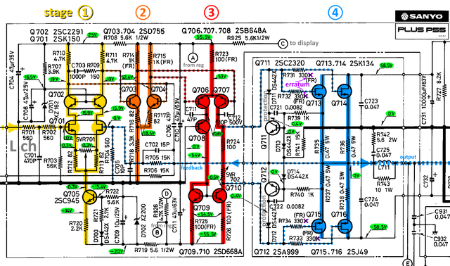
To help with restorations and potential repair of a Sanyo Plus P55, I have prepared a schematic of the left amp with stages marked in different colors: 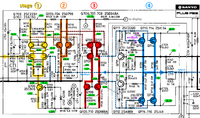 May it help all who will work on the Sanyo Plus P55. - Johannes |
|||||
|
csari0
Neuling |
#63
erstellt: 05. Nov 2021, 04:58
|
||||
|
Hi Johannes I hope all is well. Here is an update, and a question: I just got a bunch of electrolyctic capacitors, transistors, and resistors. The film capacitors are on order. Gonna start soon. Power caps are sold out everywhere, so waiting for those to be available. A quick question: The original emitter resistors are 5w. What wattage are the ones used in the mod? Are they 2 x 5w? Thanks P.S. I also just removed the transformer out of the C55 unit, it's going to be an external transformer. I will post pics when it's all done, both C55 and P55 |
|||||
|
Poetry2me
Inventar |
#64
erstellt: 06. Nov 2021, 02:58
|
||||
|
Hi Csari0, yes, caps seem to have become a scarce resource.
Good question. The original 'source resistors' (aka emitter resistors for BJT circuits) are dual-resistor parts with 2 x 5W. As described earlier in this thread, we used to replace these with 2 x single Dale CPF 3W resistors which always worked ... at first. But meanwhile there were two cases where thes burnt through. So we started to go back to using 2 x single 5W MPC (metal band, low impedance) type resistors. So this would now be my recommendation. - Johannes |
|||||
|
Broesel02
Inventar |
#65
erstellt: 06. Nov 2021, 23:32
|
||||
|
Hello Csari0 The emitter Resistors should be changed because there are treatet for about 40 Years with a high Bias - there could change there Values. And then the Amplifier begins to oscillate. The best way is to make the Resistors on the on the Gate and on the Emitter - just to be on the safe side. Wich type you use, Dale CMP or MPC Types like BPR58CR47J from KOA Speer ore whatever - that is your decision. I Think the Dale CMP Types sound a little bit better. But if you have some truoble at the power stage of the amp - the will immediatly burn down. Especially if you want to use the AMP in BTL Operation i would recommend MPC Emitter Resistors. Make all of the soldering on the little Current PCB new. There are all weak Regards Richard [Beitrag von Broesel02 am 06. Nov 2021, 23:33 bearbeitet] |
|||||
|
awtms
Neuling |
#66
erstellt: 05. Jan 2022, 21:50
|
||||
|
Hi all, i have power on my Sanyo P55 today and the leds at the right channel stays on (all green and first red). I need help to repair it. Regards. 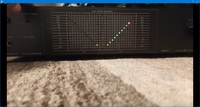 |
|||||
|
CarlM.
Inventar |
#67
erstellt: 05. Jan 2022, 22:47
|
||||
|
Hello and "welcome to the HiFi-Forum!" You should offer more information. Does the problem only concern the VU-meter? Audio signal is okay? Any hum? Did you check for V DC at the speaker terminal? BTW Are you experienced in repairing audio equipment? Do you own a multimeter and/or oscilloscope? [Beitrag von CarlM. am 05. Jan 2022, 22:48 bearbeitet] |
|||||
|
awtms
Neuling |
#68
erstellt: 05. Jan 2022, 23:00
|
||||
|
Thx for your answer. I was scared and switched off imediatly. Not checked anything.Beffore that everything is ok. Yes i have multimeter and oscilloscope. Also i have the service manual and some experiance of repairing on audio equipment. |
|||||
|
Poetry2me
Inventar |
#69
erstellt: 06. Jan 2022, 00:14
|
||||
First step in diagnosis is measuring DC offset directly at each of the two channel output point. |
|||||
|
awtms
Neuling |
#70
erstellt: 06. Jan 2022, 00:22
|
||||
|
OK. thx a lot . i will check it tomorrow . |
|||||
|
Valenzband
Inventar |
#71
erstellt: 06. Jan 2022, 02:23
|
||||
For forensic investigation, it would be good to know whether the error occurred spontaneously or whether there were signs. It might be important to know whether the device had previously been idle for a longer period, say more than a year. |
|||||
|
awtms
Neuling |
#72
erstellt: 07. Jan 2022, 20:08
|
||||
|
Hi again, I have measure DC at the output of right channel : 4.3mv The left channel is 33mv. I have check also (just visual) the pcb of vu meters. The midle LM324N of right side is deferent brant from the others. Previous owner probably has changed that. Is possible failed again? Regards |
|||||
|
Valenzband
Inventar |
#73
erstellt: 07. Jan 2022, 23:19
|
||||
|
Offset seems reasonable. Does the larger voltage correspond to the full scale reading meter? There is still a chance of main amp failure. I recommend to verify idle currents of both channels. However, unless the values are far away from nominal, do not re-adjust the corresponding pots right away; I bet the original pots show more or less corrosion, which could cause erratic or even catastrophic excursions of the idle current whenever the contact goes bad, even short term. If you feel confident, try playing some music and listen for anormal sound/noise. In that case turn off immediately. Otherwise the meter is likely the cause of failure. There are few electrolytic caps which could have suffered from extended periods of non-operation, hence my previous questionary... |
|||||
|
CarlM.
Inventar |
#74
erstellt: 07. Jan 2022, 23:23
|
||||
If you own headphones, you should use them for these tests before connecting the speakers. [Beitrag von CarlM. am 07. Jan 2022, 23:24 bearbeitet] |
|||||
|
csari0
Neuling |
#75
erstellt: 09. Jan 2022, 05:49
|
||||
|
Happy New Year!!! Well, I have not started on the P55 A little busy, and I was not feeling 100% during Christmas. Got all film caps, transistors. resistors. The power caps just arrived at digikey. these are the emitter resistors I'm looking at: https://www.digikey....08?itemSeq=381471558Let me know what you think. But I got around to finishing the C55... and finish it I did. I finished it so well, that I burned out the power transformer. I was adjusting a pot, when I hear a faint "click" come from the external PT. LED light was out. I went and hooked up my power supply. And nothing... no LED I recheck the soldering, making sure I didn't make a mistake. All my soldering was pretty solid, except... I accidentally soldered to joints together, that shouldn't have been. Fixed those two mistakes and hooked up my power supply, and... viola.... LED was back!! So... my PT is dead... need to get a new one. If any of you gentle would be as kind as to help me find the V and watts. I'm looking at the schematics... I'm no expert, so I'm guessing here. The voltage is 34.6 at 20w... so the PT I should be looking for is a dual out put 40v .5a.. If I'm wrong please correct me. PS. I was reading the thread about someone having lights out, and no sound. Plugging these units in after being idle for a longtime is a bad idea. many things can go wrong, and they often do, sometimes instantly if you are lucky, sometimes it takes days or weeks. Better build a light bulb tested to limit the wattage the unit get, a sudden jolt of wattage on parts that have been sitting idle for months or years is asking for trouble. My unit had two bad relays, I just but new ones. so my sound was cutting out. Kind regards, keep well, and have a great year!! |
|||||
|
Poetry2me
Inventar |
#76
erstellt: 09. Jan 2022, 10:55
|
||||
|
Welcome back csari0, hope you are well and the New Year is really new .. and better
Looks like a perfect choice: 5W, non-magnetic leads (copper) and ceramic core, non-inductive wire-wound, lowest temperature coefficient, ... |
|||||
|
Poetry2me
Inventar |
#77
erstellt: 09. Jan 2022, 12:12
|
||||
|
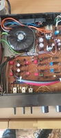
Regarding the Preamplifier Sanyo Plus C55 Sorry to hear about the transformer. Only once, I looked into my own 220VAC model transformer casing and this is a picture of what I saw:  It looks like a semi-torrodial transformer with extensive shielding (mu-metal plus a full irond encasing). Replacement parts would need secondary windings for about 2 x 24VAC (23,7VAC per winding, assuming 1V loss on rectifier and 34,5VDC rectified). I wonder if torrodial types would also work or would be flat enough and also meet expectation regarding low EMI into the audio circuit. One big question remains: What would have to be assumed as output current? My 220VAC model transformer permanently runs quite warm, around 40..45°C I guess, at least in summer when not enough heat can be dissipated by surrounding air. There are no vents whatsoever in the C55 lid either. So, try finding semi-torrodial or torrodial models and check physical size. Try estimating the wattage (VA value) and thereby the output current allowable. You may end up without the extra iron casing. Don't know what the EMI influence of the transformer will be then. - Johannes [Beitrag von Poetry2me am 09. Jan 2022, 13:05 bearbeitet] |
|||||
|
Seimalanders
Stammgast |
#78
erstellt: 09. Jan 2022, 13:04
|
||||
|
Regarding the VA (Wattage) of the PT: I think if you follow the data on the type plate (plus a bit margin) you won't get wrong. |
|||||
|
awtms
Neuling |
#79
erstellt: 09. Jan 2022, 16:40
|
||||
|
Hi again, First i want to thank you all for your help! I have checked the idle current: ≈50mv on each channel.(i think is ok). I have play music and listening from my headphones.Left and right channel sounds perfect. If you agree i think the problem is on VU metter pcb. Now i'm trying to understand the sciematics... |
|||||
|
csari0
Neuling |
#80
erstellt: 12. Jan 2022, 05:50
|
||||
|
Hello everyone... I'm on my phone, so this site appears different than on my computer. So I will keep this brief. Here is a transformer that looks promising. https://www.mouser.c...MwZnHmRNf5MYYA%3D%3DLet me know what you think. Thanks. |
|||||
|
Poetry2me
Inventar |
#81
erstellt: 12. Jan 2022, 09:52
|
||||
|
Regarding the VU Meter LED cascade display: Richard/Broesel02 reported that he knows of the following two probelms: a) Bad solder joints on the VU meter PCB b) Once, there was a defective LM324N (quadruple OpAmp) on the VU meter PCB - Johannes |
|||||
|
csari0
Neuling |
#82
erstellt: 13. Jan 2022, 06:36
|
||||
Just realized the primary is low, it should be 115v (North America) this one looks more promising: https://www.digikey....80?itemSeq=387107172I'm gonna order it, and let you know how it goes.. Best regards. |
|||||
|
Poetry2me
Inventar |
#83
erstellt: 13. Jan 2022, 09:54
|
||||
|
Replacement transformer for preamplifier Sanyo Plus C55: Careful: You will need an extremely flat model to fit in ! As I mentioned above: Try "semi-torrodial" or "torrodial" type transfomers |
|||||
|
awtms
Neuling |
#84
erstellt: 14. Jan 2022, 11:07
|
||||
|
Link for Relays of P55 (available also on mouser and digi). https://www.tme.eu/g...ctivity/9-1419111-3/And for emitter resistors 0.47ohm https://www.tme.eu/g...rs/ohmite/ag10jr47e/Regards |
|||||
|
awtms
Neuling |
#85
erstellt: 14. Jan 2022, 20:01
|
||||
|
Update for the problem with VU meter: Solved when changed 2x njm4558! Regards. |
|||||
|
CarlM.
Inventar |
#86
erstellt: 14. Jan 2022, 20:41
|
||||
|
@csari0 You will need a transformer with a maximum height of 40mm (as Johannes already wrote). I would select this one - if 71mm of diameter are available: www.digikey.de/de/pr...cs/VPT48-520/2090066other choices with less than 41mm: www.digikey.de/de/pr...UjDDGYPQFRU4lrlKSkkAtorroidal diameter 61mm https://export.rsdel...oidal-20va-2/7529309Good luck! Carl [Beitrag von CarlM. am 14. Jan 2022, 21:34 bearbeitet] |
|||||
|
Poetry2me
Inventar |
#87
erstellt: 14. Jan 2022, 21:03
|
||||
|
@awtms: ____CONTRATULATIONS on your successful repair! You now have an excellent sounding amp which will make many people envious as soon as they start listening with it.  - Johannes |
|||||
|
awtms
Neuling |
#88
erstellt: 23. Jan 2022, 13:21
|
||||
|
Dear all, Just finished revision of the first (i have 2 working as mono) Sanyo P55 folowing Richard(respect) orders. I have only one thing to say : AMAZING!!!! Compared to the other: day and night! Regards. Nick |
|||||
|
Poetry2me
Inventar |
#89
erstellt: 23. Jan 2022, 19:16
|
||||
|
Thank You for this wonderful feedback !! - Johannes |
|||||
|
awtms
Neuling |
#90
erstellt: 08. Mai 2022, 10:39
|
||||
 I have replace the transformer on my C55 because of noise when became hot. |
|||||
|
Poetry2me
Inventar |
#91
erstellt: 08. Mai 2022, 13:26
|
||||
|
Thank you, this is good information !! It looks like a torrodial type. Would you share with us what maker and model you have picked? What are the secondary winding values (voltage, max. current, VA)? - Johannes |
|||||
|
awtms
Neuling |
#92
erstellt: 08. Mai 2022, 14:24
|
||||
|
Hello Johannes, Yes, is toroidal transformer with electrostatic shield (copper foil) between coils to divert primary noise to ground.Also with magnetic shield. This is 50VA transformer with 2x24.5 Volt secondary coil. I have buy it from local market at 38. Model 255 at the catalog (Diameter:75mm Height:37mm). https://www.giatras.com/toroidal-transformersRegards. |
|||||
|
awtms
Neuling |
#93
erstellt: 08. Mai 2022, 14:44
|
||||
|
I think they send only in Greece. If you want you can send me specification of the transformer you want and i can send it to you if the cost (transformer+shipping) is acceptable. Regards. |
|||||
|
bluethor
Neuling |
#94
erstellt: 19. Jul 2023, 13:22
|
||||
|
Hallo zusammen, ich habe auch seit mehreren Jahren die P55 Endstufe und bin grundsätzlich von der Stimmwiedergabe immer wieder sehr begeistert. Auch neue Verstärker, die ich getestet habe, bringen meiner Meinung nach nicht dieses gewisse Etwas. Da meine Endstufe noch keine Revision bekommen hat, fehlt es leider etwas an der Detailauflösung, wenn ich sie mit neuen Endstufen vergleiche. Daher würde ich sie gerne überarbeiten lassen. Ich persönlich bin dazu leider nicht in der Lage. Habt Ihr einen Tipp, wer hiermit Erfahrung hat und dies gegen eine faire Bezahlung machen könnte? Ich wohne im Raum Düsseldorf. Vielen Dank! |
|||||
| |||||

|
|
||||
Gehe zu Seite: |vorherige| Erste Letzte
| Das könnte Dich auch interessieren: |
|
Sanyo Plus Series C55/P55 rwhenn am 20.09.2014 – Letzte Antwort am 09.03.2015 – 15 Beiträge |
|
Frage zu einer Revision Dj_Pillepenny# am 27.10.2024 – Letzte Antwort am 27.10.2024 – 2 Beiträge |
|
Sanyo plus series A35 brummt 77er am 14.09.2017 – Letzte Antwort am 27.09.2017 – 55 Beiträge |
|
Wangine WFA-220 Endstufe, eine kleine "Revision" _ES_ am 18.02.2022 – Letzte Antwort am 02.03.2022 – 18 Beiträge |
|
Sanyo Plus Q 60 Tonarmlift reparieren Hippman am 29.08.2013 – Letzte Antwort am 27.04.2019 – 14 Beiträge |
|
Revision Sansui C-2102 Uwe_1965 am 18.01.2018 – Letzte Antwort am 02.01.2020 – 40 Beiträge |
|
Probleme mit Plattenspieler Sanyo plus Q50 -ananas- am 27.10.2009 – Letzte Antwort am 08.02.2011 – 3 Beiträge |
|
McIntosh komplette Revision Mister_McIntosh am 20.12.2020 – Letzte Antwort am 25.12.2020 – 3 Beiträge |
|
Revision Yamaha M-80 Lionwm am 12.12.2014 – Letzte Antwort am 19.01.2015 – 5 Beiträge |
|
Revision Sansui B-2102 Uwe_1965 am 19.04.2017 – Letzte Antwort am 08.03.2022 – 217 Beiträge |
Anzeige
Produkte in diesem Thread


Aktuelle Aktion


Partner


Top 10 Threads in Hifi-Klassiker der letzten 7 Tage
- Kondensator ersetzen mit höherem Wert - zulässig?
- WD40 als Kontaktspray?
- Grundig R-2000 Mutingproblem
- Entstörkondensator- Beschriftung und deren Bedeutung
- Dreh - Lautstärkeregler defekt? reagiert falsch oder gar nicht Aiwa NSX AV 320
- Problem bei Reparatur von Pioneer CT 676
- Marantz / Superscope CD-302A Tape Deck
- "Tapedeck-Reparatur" Thread
- Welche Glassicherungen/Feinsicherungen Flink oder Träge ?
- Akai GX-260D-Überholung, Transistorersatztypen?
Top 10 Threads in Hifi-Klassiker der letzten 50 Tage
- Kondensator ersetzen mit höherem Wert - zulässig?
- WD40 als Kontaktspray?
- Grundig R-2000 Mutingproblem
- Entstörkondensator- Beschriftung und deren Bedeutung
- Dreh - Lautstärkeregler defekt? reagiert falsch oder gar nicht Aiwa NSX AV 320
- Problem bei Reparatur von Pioneer CT 676
- Marantz / Superscope CD-302A Tape Deck
- "Tapedeck-Reparatur" Thread
- Welche Glassicherungen/Feinsicherungen Flink oder Träge ?
- Akai GX-260D-Überholung, Transistorersatztypen?
Top 10 Suchanfragen
Forumsstatistik
- Registrierte Mitglieder931.107 ( Heute: 1 )
- Neuestes Mitgliedkxlas
- Gesamtzahl an Themen1.564.735
- Gesamtzahl an Beiträgen21.864.596
