| HIFI-FORUM » Reparatur & Wartung » Hifi-Klassiker » Technics SE-A5 mk2 - tot wie die Maus | |
|
|
||||
Technics SE-A5 mk2 - tot wie die Maus+A -A |
|||||||
| Autor |
| ||||||
|
Hcmetz
Neuling |
#1
erstellt: 21. Dez 2023, 01:09

|
||||||
|
Hallo! Also, ich habe den im Titel angegebenen Verstärker, der leider überhaupt nicht funktioniert (ist so auch schon zu mir gekommen). Wenn ich anschalte - nichts. Ich habe ein paar Ansätze versucht
Ich brauche aber zuallererst die Schaltpläne, inklusive der Voltages (ich glaube, daß service manual gibt die nicht an). Ich habe hier auf dem Forum nur einen Schaltplan, aber für die ältere Version, gesehen. Danke für jede Hilfe!
|
|||||||
|
CarlM.
Inventar |
#2
erstellt: 21. Dez 2023, 01:14
|
||||||
|
Text nachträglich gelöscht! Ursprünglicher Text beruhte auf der Verwechselung des Vorverstärkers mit der Endstufe. Nachdem Rabia Sorda darauf aufmerksam gemacht hat, wird im Folgenden eine korrigierte Antwort gegeben ... [Beitrag von CarlM. am 21. Dez 2023, 19:26 bearbeitet] |
|||||||
|
|
|||||||
|
Rabia_sorda
Inventar |
#3
erstellt: 21. Dez 2023, 19:02
|
||||||
|
Hi Carl, Ich glaube du hast dich mit dem Technics-Type vertan, denn es handelt sich hier um die Endstufe SE-A5 und nicht um den SU-A6. TECHNICS SE-A5MK2 SM [Beitrag von Rabia_sorda am 21. Dez 2023, 19:03 bearbeitet] |
|||||||
|
CarlM.
Inventar |
#4
erstellt: 21. Dez 2023, 19:13
|
||||||
|
Hallo Karsten, da habe ich mich tatsächlich vertan ... vermutlich, weil die beiden häufig als Combi genutzt werden. Dann werde ich mir das andere Service Manual mal zu Gemüte führen ... soweit der TE sich nochmals melden sollte ... Carl |
|||||||
|
Hcmetz
Neuling |
#5
erstellt: 21. Dez 2023, 19:32
|
||||||
|
Ja, hallo! SE-A5 mk2, wie gesagt. Das Problem ist, daß ich nicht der Techniker bin, sondern der Eigentümer des Verstärkers (= rudimentäres Technikverständnis), und der Techniker spricht kein Deutsch das Service manual hatten wir schon - mein Techniker hat mir aber gesagt, daß da die Spannungsangaben unvollständig seien oder fehlten? Ich hatte in einer anderen Diskussion dazu hier eine gute Abbildung gefunden, wo jemand, glaube ich, die Voltages eingetragen hatte aber für einen mk1. Ich warte jetzt ein bißchen auf mehr Details von seiner Seite Stay tuned Danke HC |
|||||||
|
CarlM.
Inventar |
#6
erstellt: 21. Dez 2023, 19:34
|
||||||
|
Neue Antwort. Du solltest zunächst präzise mitteilen, was Du unter "nichts" verstehst. Leuchtet auch keine LED? Ist kein Relais-Klacken zu hören? Desweiteren interessiert, welchen Vorverstärker Du verwendest und wie Du ihn angeschlossen hast. Wenn es tatsächlich so ist, dass es keinen Unterschied zu einem nicht mit Netzspannung verosrgten Gerät gibt, solltest Du die diversen Sicherungen prüfen. Danach sollten die im Service Manual (S. 7 von 26 des von Rabia Sorda verlinkten Manuals; Nummerierung nach PDF-Reader) angegebenen Spannungen VAC der Sekundärwicklungen beider Trafos geprüft werden. [Beitrag von CarlM. am 21. Dez 2023, 19:36 bearbeitet] |
|||||||
|
CarlM.
Inventar |
#7
erstellt: 21. Dez 2023, 19:39
|
||||||
|
Ich habe das von Rabia Sorda verlinkte Manual nochmals geprüft. Die wichtigsten Spannungen sind in den enthaltenen Schaltplänen vorhanden. Gibt es eine Möglichkeit, direkt mit dem Techniker zu kommunizieren? Das ist meistens zielführender. |
|||||||
|
Hcmetz
Neuling |
#8
erstellt: 21. Dez 2023, 21:47
|
||||||
|
Könnte mein techie hier, aber auf English, antworten? Sonst gehts halt nur indirekt
|
|||||||
|
CarlM.
Inventar |
#9
erstellt: 21. Dez 2023, 22:05
|
||||||
|
Kein Problem. Der Link zum Service Manual mit den Referenzspannungen ist ja sowieso von der Sprache nahezu unabhängig. |
|||||||
|
Hcmetz
Neuling |
#10
erstellt: 22. Dez 2023, 10:10
|
||||||
|
Hello everyone! I am the technician. As the owner has stated he bought the power amp in a non functioning state. I was told the amp would turn on then go into a protect mode. I opened the chassis and both mains fuses (T4) were open. I replaced them and turned on the amp with a limiter. R374 connecting to Q330 Immediately went to 450°F so I turned it off. I had an infrared thermometer on it just in case. I then added a variable transformer to bring the voltage up slowly. At 10v ac supply R374 was heating up the same way. I removed Q330, R374 stayed cool. I tested the transistor in my tester and it read unknown/damaged. At 20v ac, thermistor TH302 started overheating and there was a puff of smoke from the left side of the amp. Around q333/335 It looks like the previous owner had all of the output transistors replaced. Hardware is missing, there is thermal paste everywhere, and the underside of the PCB has flux residue all around the transistors My issue is I can't even turn this amp on to test voltages and the service manual I have didn't reference any. I no longer have the amp as I informed my client that there is zero garuntee on this working and I don't want to waste money/time, he now has the amp back in his possession. Have any of you experience these symptoms? |
|||||||
|
CarlM.
Inventar |
#11
erstellt: 22. Dez 2023, 14:01
|
||||||
|
Thank you for the detailed information. My opinion: If the preowner tried to repair already without any success there is no base to compare with other cases. Maybe the substitutes transistors are fakes (?) ... My strategy would be: - removing of the pcb ... cleaning ... checking for defective soldering - removing all transistors and checking outside - checking theother parts on the pcb without desoldering - replacement of all transistors ... checking outside by using a variable double-power supply btw. The linked service manuals contains the most important voltages in the schematics (see post of rabia sorda). best wishes Carl |
|||||||
|
Poetry2me
Inventar |
#12
erstellt: 23. Dez 2023, 04:37
|
||||||
|
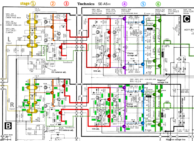
Above, there was a question about the voltages within the schematic. Just wanted to point you to this other thread http://www.hifi-foru...ead=19523&postID=6#6with this colorized schematic I once made:
Hope it helps. - Johannes |
|||||||
|
Hcmetz
Neuling |
#13
erstellt: 23. Dez 2023, 04:56
|
||||||
|
Hello Johannes, Yes, I saw that and had handed it to my technician after he had already spent some time on it. When I bought the amp I was very happy as thus is among the most beautiful technics amps (I started my HiFi trajectory with a nice SU-7700 ) but unfortunately, I have to find that this is probably too much to have fixed this is better for a passion project for someone who can fix it himself a part-by-part analysis and repair paid for by the hour feels not feasible Oh, well HC |
|||||||
|
Poetry2me
Inventar |
#14
erstellt: 23. Dez 2023, 19:38
|
||||||
|
Hi HC, indeed, this amp is beautiful in many ways, including the very heart of it: The circuit design. I hope you find someone who has the passion and skills to unleash the unquesionable high-end potential of this wonderful amp. And I am not only speaking of just a recap. - Johannes |
|||||||
|
Poetry2me
Inventar |
#15
erstellt: 23. Dez 2023, 22:02
|
||||||
|
I just realized: The MK II version has a different ciscuit design. Alone, the way the schematic is drawn already gives me the creeps. Much more complicated (as opposed to complex), takes you extra time to read and understand. I found at least one erratum (around R351 where left ch feedback hits ground) which I corrected in my version. I suspect more to be found, e.g. in stage 3. 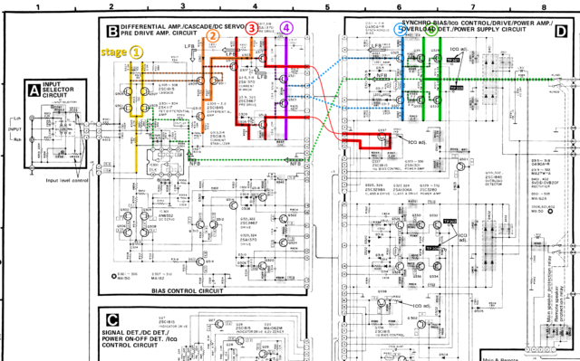 Hope this helps to better understand the MK II version. LFB stands für Local FeedBack NFB stands for Negative FeedBack The BIAS CONTROL circuit "outrigger" in stage 3 (red) is a regular idle current Vbe circuit as we know it, just drawn the way a contortionist would do it ;-) BTW: The OpAmp is just a plain vanilla DC servo. - Johannes |
|||||||
|
Hcmetz
Neuling |
#16
erstellt: 24. Dez 2023, 00:39
|
||||||
|
Thank you Johannes - yeah, I had asked above if that was the same / similar to the mk1
so its not. |
|||||||
|
Hcmetz
Neuling |
#17
erstellt: 24. Dez 2023, 08:37
|
||||||
|
Hello again, tech here. My client asked me to upload the photos I took of the inside of the chassis. I believe I uploaded them correctly, I'm using Google translate to read the web page, it's possible something was lost in translation. 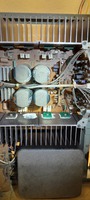 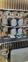 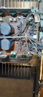 |
|||||||
|
Poetry2me
Inventar |
#18
erstellt: 25. Dez 2023, 12:41
|
||||||
|
Schematic of Technics SE-A5 MK2 applies:
When reading this I was in good hope you would limit excess current with an lightbulb (oldschool wolfram wire, halogen will also do) of true 100W or similar. The simplest way of protecting the remaining parts in the amp.
Not good. Q330 is one of two parallel power transistors in final stage 6 (green) in the right channel. Looks like Q330 is burnt through (zero Ohms) between Collector and Emitter. Thus R374 - as it's companion Emitter Resistor - is directly exposed to full rail supply and will soon burn through as well. First thing that comes to my mind now: Use an Ohmmeter to check if the Collector-Base path of Q330 also has 0 Ohms. If yes, the whole previous stage 5 (blue) is suspicious of having damage as well. It needs to be checked anyway, including it's resistors. Second thing: From now on ALWAYS (A-L-W-A-Y-S) use the lightbulb limiter, NEVER just rely on the variable transformer alone, since it will NOT prevent further damage. This is a lesson I had to discover the hard way, after learning it the wrong way (var-transformer-only) in a professional repair shop.
Further damage done due to missing limiter. Question: Q333/335 are left channel. So far the damage was in right channel. Could it be you meant Q334/336 in the right channel?
This could be one of the "classic" cases, where someone (previous owner?) has focused on the transistors only. If not taken care of, damaged resistors will annihilate any repair effort immediately, if no lightbulb is used. Maybe the previous owner has used a lighbulb when turning on. He replaced the transistors but saw that excess current still flows and decided to sell the device. In good intention, He may have removed the fuses intentionally to prevent immediate damage with the next turn-on. - Johannes [Beitrag von Poetry2me am 25. Dez 2023, 13:39 bearbeitet] |
|||||||
|
Hcmetz
Neuling |
#19
erstellt: 28. Dez 2023, 04:07
|
||||||
|
Ja, wollte dann noch einmal Danke sagen für die Hilfe. Werde jetzt versuchen, den Verstärker für Ersatzteile zu verkaufen. Schade! Guten Rutsch jedenfalls an alle hier. HC |
|||||||
|
Poetry2me
Inventar |
#20
erstellt: 28. Dez 2023, 20:48
|
||||||
|
Tut mir Leid das zu hören. Jedenfalls wird es nicht unmöglich sein, diesen Amp zu reparieren. Aber man muss Strombegrenzung durch vorgeschaltete Glühbirne verwenden und man muss auch einige der Bauteile der letzten zwei Stufen erst noch durchmessen. - Johannes |
|||||||
| |||||||

|
|
||||
| Das könnte Dich auch interessieren: |
|
Technics se A5 MK2 Spezialist gesucht schwarzrund am 30.01.2018 – Letzte Antwort am 04.02.2018 – 4 Beiträge |
|
Technics SE-A5 Probleme_Bauteile Gogooortah am 21.05.2018 – Letzte Antwort am 12.07.2018 – 11 Beiträge |
|
Technics SE-A5: Protection geht nicht aus GG71 am 30.12.2012 – Letzte Antwort am 01.01.2013 – 8 Beiträge |
|
Technics SE-A5 - Propleme im linken Kanal der_tommy am 21.04.2023 – Letzte Antwort am 22.04.2024 – 9 Beiträge |
|
Technics MK2-Linker Kanal tot, wenn geerdet! wurstelic am 24.07.2011 – Letzte Antwort am 24.07.2011 – 2 Beiträge |
|
TECHNICS SE-A 1000 Mk2 + Reference borderbenz am 26.01.2013 – Letzte Antwort am 22.02.2016 – 31 Beiträge |
|
SE-A5 ein Pegelmeter geht nicht ThomasVeihoff am 13.01.2022 – Letzte Antwort am 17.01.2022 – 17 Beiträge |
|
Technics SE-A5 - was ist das hier für ein Relais? toddrundgren am 12.05.2015 – Letzte Antwort am 13.05.2015 – 10 Beiträge |
|
Technics SU-A6 MK2 Teildefekt? *Holly* am 24.12.2020 – Letzte Antwort am 14.02.2021 – 65 Beiträge |
|
Technics SE-A3 Problem Oli_Oliver am 11.07.2024 – Letzte Antwort am 24.07.2024 – 8 Beiträge |
Foren Archiv
2023
Anzeige
Produkte in diesem Thread


Aktuelle Aktion


Partner


Top 10 Threads in Hifi-Klassiker der letzten 7 Tage
- Kondensator ersetzen mit höherem Wert - zulässig?
- WD40 als Kontaktspray?
- Grundig R-2000 Mutingproblem
- Entstörkondensator- Beschriftung und deren Bedeutung
- Dreh - Lautstärkeregler defekt? reagiert falsch oder gar nicht Aiwa NSX AV 320
- Problem bei Reparatur von Pioneer CT 676
- Marantz / Superscope CD-302A Tape Deck
- "Tapedeck-Reparatur" Thread
- Welche Glassicherungen/Feinsicherungen Flink oder Träge ?
- Akai GX-260D-Überholung, Transistorersatztypen?
Top 10 Threads in Hifi-Klassiker der letzten 50 Tage
- Kondensator ersetzen mit höherem Wert - zulässig?
- WD40 als Kontaktspray?
- Grundig R-2000 Mutingproblem
- Entstörkondensator- Beschriftung und deren Bedeutung
- Dreh - Lautstärkeregler defekt? reagiert falsch oder gar nicht Aiwa NSX AV 320
- Problem bei Reparatur von Pioneer CT 676
- Marantz / Superscope CD-302A Tape Deck
- "Tapedeck-Reparatur" Thread
- Welche Glassicherungen/Feinsicherungen Flink oder Träge ?
- Akai GX-260D-Überholung, Transistorersatztypen?
Top 10 Suchanfragen
Forumsstatistik
- Registrierte Mitglieder931.200 ( Heute: 3 )
- Neuestes MitgliedFrancois_Villon
- Gesamtzahl an Themen1.564.948
- Gesamtzahl an Beiträgen21.872.994
