| HIFI-FORUM » Reparatur & Wartung » Hifi-Klassiker » Grundig R1000 | |
|
|
||||
Grundig R1000+A -A |
||
| Autor |
| |
|
camuscamus
Neuling |
#1
erstellt: 29. Okt 2021, 19:25

|
|
|
Hallo und danke, dass Sie meine Frage(n) lesen und berücksichtigen. Ich besitze den Grundig R1000 Verstärker. Plötzlich gibt der linke Kanal keinen Ton mehr aus. Ich habe die Lautsprecher getauscht und den funktionierenden rechten Kanal auf den linken Kanal übertragen, kein Ton. Ich möchte also vermuten, dass das Problem bei einem Kanal liegt. Ich habe einen Schaltplan gefunden, der hier kostenlos ist: https://elektrotanya.com/grundig_r1000.pdf/download.html#dlIch freue mich über alle Vorschläge, die in die richtige Richtung weisen, um das Problem zu lösen. Vielen Dank im Voraus. Übersetzt mit www.DeepL.com/Translator (kostenlose Version)I don't speak German very well, so if you can help me in English, the sun I pray, will always shine on your path. |
||
|
Rabia_sorda
Inventar |
#2
erstellt: 29. Okt 2021, 21:21
|
|
|
Hello, Often only the switches and potentiometers in the signal path are oxidized and for this they should be operated about 50 times. This loosens any oxidation that may be present on the contacts. Otherwise there is a real defect. For this purpose, however, the error can be in the preamplifier or also in the power amplifier. Measurements should be taken for this, because with remote diagnosis it is rather difficult to say. Is it at every line-in? [Beitrag von Rabia_sorda am 29. Okt 2021, 21:53 bearbeitet] |
||
|
|
||
|
Elektronator
Stammgast |
#3
erstellt: 29. Okt 2021, 23:57
|
|
|
Hallo camuscamus, ist das Verhalten bei allen Quellen (UKW Tuner, MW oder LW, TB und Phono) gleich? Welche Messmittel hast du? (z. B. Multimeter, Oszilloskop) Hello camuscamus, ist the effect the same for all sources (FM tuner, AM tuner (MW or LW), TB and phono)? Which measurement equipment do you have? (e.g. multimeter, oscilloskope) |
||
|
camuscamus
Neuling |
#4
erstellt: 30. Okt 2021, 00:32
|
|
|
Zuerst muss ich sagen, VIELEN DANK, dass Sie überhaupt geantwortet haben. Ich habe keine Antwort erwartet, weil ich dachte, ich hätte Leute beleidigt, die auf Englisch schreiben. Das ist großartig. Ich fühle mich willkommen. DANKE! Ich habe ein Multimeter. Wenn jemand einen Blick auf den Schaltplan werfen kann und mir sagen kann, wo und was ich wie überprüfen muss, habe ich das Gefühl, dass das Problem bereits gelöst ist. Ich danke Ihnen! Ja, der Effekt ist der gleiche, unabhängig vom Eingang: TAPE, PHONO, TUNER, ETC Übersetzt mit www.DeepL.com/Translator (kostenlose Version)First, I must say, THANK YOU VERY MUCH, for responding at all. I did not expect a response, thinking I have insulted people writing in English. This is great. I feel welcomed. THANK YOU! I have a multi meter. If someone can look at the schematic and tell me where and what to check, and how, I feel already, this is solved. Thank you! Yes, the effect is the same, no matter the input; TAPE, PHONO, TUNER, ETC [Beitrag von camuscamus am 30. Okt 2021, 00:33 bearbeitet] |
||
|
camuscamus
Neuling |
#5
erstellt: 30. Okt 2021, 00:38
|
|
|
Zuerst muss ich sagen, VIELEN DANK, dass Sie überhaupt geantwortet haben. Ich habe keine Antwort erwartet, weil ich dachte, ich hätte Leute beleidigt, die auf Englisch schreiben. Das ist großartig. Ich fühle mich willkommen. DANKE! Ja, der Effekt ist der gleiche, unabhängig vom Eingang: TAPE, PHONO, TUNER, ETC Wenn Sie sich bitte den Schaltplan ansehen und mir sagen, was ich wie überprüfen soll, werde ich das sofort tun. Übersetzt mit www.DeepL.com/Translator (kostenlose Version)First, I must say, THANK YOU VERY MUCH, for responding at all. I did not expect a response, thinking I have insulted people writing in English. This is great. I feel welcomed. THANK YOU! Yes, the effect is the same, no matter the input; TAPE, PHONO, TUNER, ETC If you please look at the schematic and tell me what to check and how, I will do it right away. Danke! Berlin |
||
|
Elektronator
Stammgast |
#6
erstellt: 30. Okt 2021, 15:15
|
|
|
Hello camuscamus, did you operate all switches and potentiometers several times, as proposed from Rabia_sorda? This test will detect contact problems in the appropriate control element. If a control element contact is not the cause: The error can be in the preamplifier or also in the power amplifier, as Rabia_sorda has already noted. I recommend to measure the DC voltages of the base potentials of T34 and T35 against ground (volume potentiometer set to minimum). These base nodes are the inputs of the left and right power amplifiers. Both voltages shall be in the range 0...60 mV. If yes, connect both base nodes. This connection enforces mono mode. If one of the base voltages is outside of this range, do not connect the nodes to prevent damage of the other power amplifier. With connected base nodes increase the volume: If both speaker outputs are now working, the failure is in the left preamplifier part. If the left speaker output is still not working, the failure is in the left power amplifier part. Then you should measure the three voltages of all transistors in the appropriate amplifier part (volume potentiometer set to minimum). |
||
|
camuscamus
Neuling |
#7
erstellt: 02. Nov 2021, 21:48
|
|
|
Hello Thank you very much for your help and contributions. I have been busy on this. I have done what Rabia_sorda proposed. I have moved the switches and potentiometers more than 50 times. I bought a can of contact cleaner. That did something, the cracks when you move the switches and potentiometers are gone. But the problem of the channel is there. I found the the base potentials of T34 and T35. Perhaps because I did not make the correct selection on my multimeter, the readings were either 0 or very high on both. 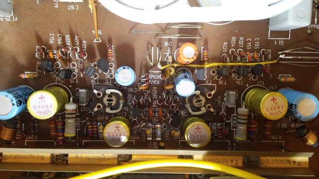 I have shared the pictures of the the base potentials of T34 and T35. And my multimeter. Please when you reply, say what selection on my multimeter I must make, and also how I must make the measurements on the base potentials of T34 and T35. I am very grateful and happy for your support. Thank you! Danke! Danke! 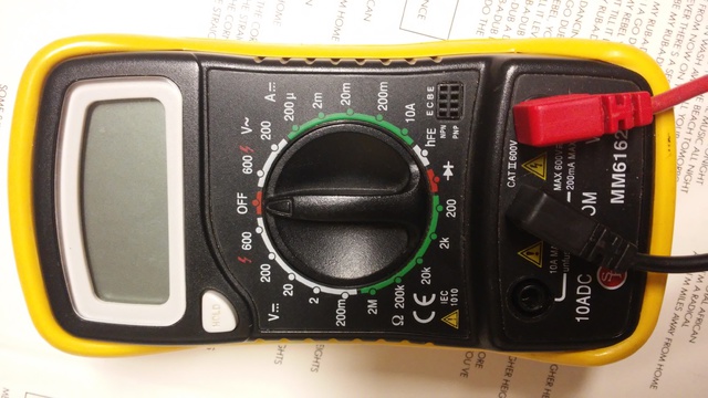  [Beitrag von camuscamus am 02. Nov 2021, 21:50 bearbeitet] |
||
|
Ingor
Inventar |
#8
erstellt: 03. Nov 2021, 17:43
|
|
|
To measure DC Voltage turn the knob into the position of 20 V =. The black cord to ground and the red to the base of the transistor. When the reading is below 2 V turn the knob into the position 2 V =. Then you get a more accurate value of the voltage. Be carefull don´t make a short. And before you use this multimeter on the Grundig try to test something else before. Never use the section with the "A" unless you know what you are doing. Otherwise you make a short. |
||
|
camuscamus
Neuling |
#9
erstellt: 03. Nov 2021, 23:28
|
|
|
Dear Ingor, Thank you very much. I put the dial to 20, the 20 to the left of the multimeter, which is the 20 V =. I put the black probe of the multimeter to the body of the amplifier and used the red probe to the base of the transistor. I got nothing. I then turned the knob on the multimeter to 2. Here are the results: Both T35 and T34 transistors have 3 pins each. On T35 Pin C = -.002 Pin E = 0 (no change in the meter display which at default was .000) Pin B = -.002 On T34 Pin C = -.002 Pin E = 0 (no change in the meter display which at default was .000) Pin B = -.001 Before the test, the multimeter was tested on a AAA battery. And it tested well on the 2 V. Thank you very much. Now, what's the next step? I feel like we've made some progress, but I rely on you, the experts, to confirm. |
||
|
Ingor
Inventar |
#10
erstellt: 04. Nov 2021, 01:02
|
|
Try what Elektronator wrote. |
||
| ||

|
|
||||
| Das könnte Dich auch interessieren: |
|
Grundig R1000: Linker Kanal leiser außer bei Radiowiedergabe olimuc am 30.10.2024 – Letzte Antwort am 02.11.2024 – 24 Beiträge |
|
Grundig R1000 will mich vereimern. Pimok am 09.03.2010 – Letzte Antwort am 09.03.2010 – 2 Beiträge |
|
Grundig R1000 Hilfe ! deilbachtaler am 20.01.2010 – Letzte Antwort am 23.01.2010 – 7 Beiträge |
|
Restauration Grundig R1000 (Knöpfe + Lampe) kuni1 am 20.02.2007 – Letzte Antwort am 25.09.2012 – 4 Beiträge |
|
Grundig V2000 - ein Kanal verzerrt bernnbaer am 01.07.2021 – Letzte Antwort am 01.07.2021 – 3 Beiträge |
|
Grundig R1000 Netzteil i.O. Endstufe ohne Funktion Igge83 am 03.01.2017 – Letzte Antwort am 04.01.2017 – 3 Beiträge |
|
Probleme/Fragen bezüglich Grundig R1000 m.karl am 23.12.2011 – Letzte Antwort am 14.02.2012 – 14 Beiträge |
|
Grundig SXV6000 Krachen linker Kanal Walter9 am 23.11.2015 – Letzte Antwort am 16.12.2015 – 8 Beiträge |
|
Grundig R1000, Feinsicherung löst aus, Seilzug hängt Bello-Ben am 11.11.2010 – Letzte Antwort am 30.07.2012 – 9 Beiträge |
|
Grundig R7500 rechter Kanal defekt axel.jahr am 03.02.2018 – Letzte Antwort am 21.02.2018 – 21 Beiträge |
Anzeige
Produkte in diesem Thread


Aktuelle Aktion


Partner


Top 10 Threads in Hifi-Klassiker der letzten 7 Tage
- Kondensator ersetzen mit höherem Wert - zulässig?
- WD40 als Kontaktspray?
- Grundig R-2000 Mutingproblem
- Entstörkondensator- Beschriftung und deren Bedeutung
- Dreh - Lautstärkeregler defekt? reagiert falsch oder gar nicht Aiwa NSX AV 320
- Problem bei Reparatur von Pioneer CT 676
- Marantz / Superscope CD-302A Tape Deck
- "Tapedeck-Reparatur" Thread
- Welche Glassicherungen/Feinsicherungen Flink oder Träge ?
- Akai GX-260D-Überholung, Transistorersatztypen?
Top 10 Threads in Hifi-Klassiker der letzten 50 Tage
- Kondensator ersetzen mit höherem Wert - zulässig?
- WD40 als Kontaktspray?
- Grundig R-2000 Mutingproblem
- Entstörkondensator- Beschriftung und deren Bedeutung
- Dreh - Lautstärkeregler defekt? reagiert falsch oder gar nicht Aiwa NSX AV 320
- Problem bei Reparatur von Pioneer CT 676
- Marantz / Superscope CD-302A Tape Deck
- "Tapedeck-Reparatur" Thread
- Welche Glassicherungen/Feinsicherungen Flink oder Träge ?
- Akai GX-260D-Überholung, Transistorersatztypen?
Top 10 Suchanfragen
Forumsstatistik
- Registrierte Mitglieder931.209 ( Heute: 1 )
- Neuestes MitgliedTrenubis
- Gesamtzahl an Themen1.564.965
- Gesamtzahl an Beiträgen21.873.326
