| HIFI-FORUM » Reparatur & Wartung » Elektronik (Stereo&Surround) » Akustikforschung a-05 klingt nicht | |
|
|
||||
Akustikforschung a-05 klingt nicht+A -A |
||
| Autor |
| |
|
Antonello4923
Schaut ab und zu mal vorbei |
#1
erstellt: 03. Jul 2021, 16:52

|
|
|
hallo Freunde Entschuldigung, mein Deutsch, aber ich benutze Google Translate deshalb Ich habe den obigen Verstärker mit folgendem Defekt leuchtet, aber es geht kein Licht an die enden sind ok alle überprüften kleinen Transistoren sind in Ordnung Ich habe die Spannungen an der Gleichrichterbrücke gemessen und habe das Minus und Plus 41 Volt aber es hört sich gar nicht an das rote Licht am Lautstärkepotentiometer ist aus, da alle Eingangslichter aus sind Ich weiß nicht, was ich noch überprüfen soll Ich habe lc7818 geändert Tc4013bp Lc4966 ohne positives Ergebnis mir bleibt nur noch die kondensatoren zu tauschen die Widerstände sind ok |
||
|
CarlM.
Inventar |
#2
erstellt: 03. Jul 2021, 17:13
|
|
|
Du bist Italiener? Leider ist die Qualität der Übersetzung nicht sehr gut. Du kannst zusätzlich in Deiner Muttersprache schreiben oder besser Englisch. Das Gerät ist sicherlich ein Acoustic Research A-05. Da es ein Name ist, sollte man dies nicht übersetzen. Leider habe ich noch kein Service Manual gefunden. Zu derselben Modellreihe gehören die Modelle A3 und A7 (nicht A4 und A6). https://www.hifi-wiki.de/index.php/Acoustic_Research_A-05Es ist immer sehr hilfreich, wenn Photos zur Verfügung gestellt werden. Dann kann man besser helfen, wenn kein Schaltplan vorhanden ist. Zum Hochladen der Photos musst Du die Funktion "IMG" nutzen. [Beitrag von CarlM. am 03. Jul 2021, 17:15 bearbeitet] |
||
|
|
||
|
Antonello4923
Schaut ab und zu mal vorbei |
#3
erstellt: 04. Jul 2021, 05:16
|
|
|
Buongiorno e buona domenica si sono italiano vivo in Sardegna purtroppo non ho nessun schema per questo A-05 inseriro delle foto al piu presto grazie |
||
|
Poetry2me
Inventar |
#4
erstellt: 04. Jul 2021, 07:38
|
|
|
Ich habe Service Manuals für Acoustic Research Model A-04 und Model A-06 im Internet gefunden (elektrotanya.com oder hifiengine.com). Leider nicht für das Model A-05. Aber die Modelle sind sehr ähnlich. Manche Schaltungsteile sind sogar gleich. Unterschiede gibt es im Power Supply und A-06 hat ein Motor Volume Potentiometer. Ich vermute, man kann viel über den A-05 lernen durch "Interpolation" der beiden Schaltpläne. Schaltplan für A-04: 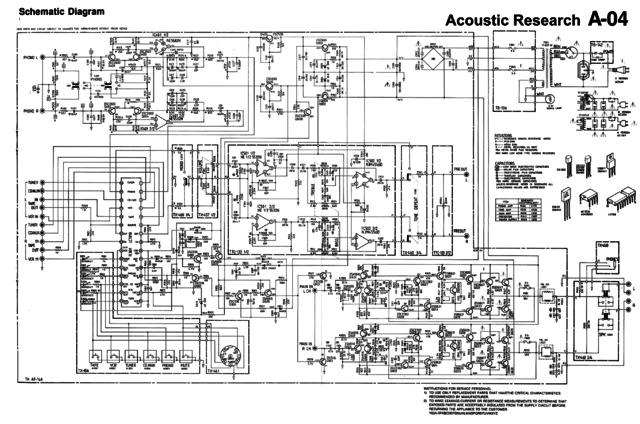 Schaltplan für A-06 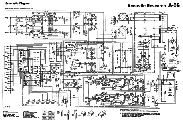 Ich hoffe das hilft bei der Fehlersuche. - Johannes [Beitrag von Poetry2me am 04. Jul 2021, 07:38 bearbeitet] |
||
|
Antonello4923
Schaut ab und zu mal vorbei |
#5
erstellt: 04. Jul 2021, 18:13
|
|
|
Thank you for your help I have come to a point where there is no power somewhere for example the little light on the volume potentiometer where does it get current from? checking where the wires are soldered on the circuit I find no voltage but then I get lost |
||
|
CarlM.
Inventar |
#6
erstellt: 04. Jul 2021, 19:47
|
|
|
1. Disconnect the amplifier from mains. 2. Open the case. 3. Check the four fuses. The most important fuses are marked by the yellow and red arrows. They belong to the power supply. The other two fuses are protecting the loudspeakers which are connected to the power amp. Please check and post your feedback. 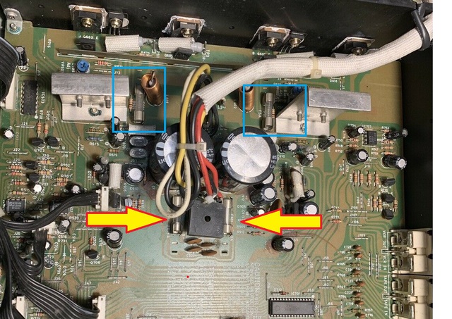 1. Scollegare l'amplificatore dalla rete. 2. Aprire il caso. 3. Controllare i quattro fusibili. I fusibili più importanti sono contrassegnati dalle frecce gialle e rosse. Fanno parte dell'alimentatore. Gli altri due fusibili proteggono gli altoparlanti che sono collegati all'amplificatore di potenza. Si prega di controllare e inviare il tuo feedback. How to present images. 1. Choose button Img 2. Follow steps in the image:  |
||
|
CarlM.
Inventar |
#7
erstellt: 04. Jul 2021, 19:59
|
|
|
@Johannes Wie genau kennst Du selbst diese Geräte? Ich frage, weil der A-05 eigentlich zur Modellreihe mit A-03 und A-07 gehört. Vom A-03 weiss ich aus dem SM,. dass die Power-Anzeige eine LED ist. Bei den Modellen A04 und A-06 ist es hingegen eine normale Glühlampe, die direkt aus einer eigenen Sekundärwicklung gespeist wird. Wenn also die Power-Leuchte nicht geht, wären die zu ziehenden Schlüsse sehr unterschiedlich ... defekter Trafo (oder Netzschalter) vs. Netzteilfehler. |
||
|
Antonello4923
Schaut ab und zu mal vorbei |
#8
erstellt: 05. Jul 2021, 06:26
|
|
|
So .... the fuses and the first thing I checked and they are intact the amplifier itself turns on but the input LEDs and the one that should light up on the volume knob are off I measured the quiescent current and it is exact referring to the sm a-04 I checked if there was any dc at the speaker output and there is none the switch works because if I put a bulb in series with the power supply as I press it, the bulb flashes I'll post the photos today ... in the meantime, thanks again |
||
|
Poetry2me
Inventar |
#9
erstellt: 05. Jul 2021, 14:28
|
|
|
@Carl: Ich hatte mal einen A-07 auf meinem Tisch. Leider hatte ich kein Service Manual und keinen Schaltplan. Er hatte einen Defekt bei den Lötstellen der Cinch Input Buchsen hinten. 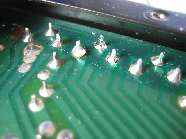 Der gesamte A-07 sieht so aus: 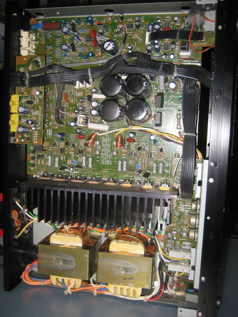  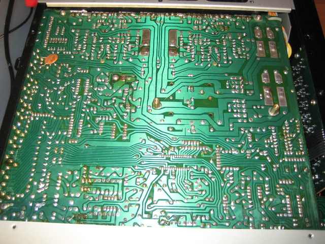 Ich sehe beim A-07 zwei Transformatoren und zwei Gleichrichter. Man muss an den großen Elektrolytkondensatoren messen, ob die Spannungen von ca. +45V und -45V (das ist eine Schätzung, ich habe keine Erinnerung) dort existieren. Auch die sekundären Transformator Wicklungen würde ich prüfen. - Johannes |
||
|
CarlM.
Inventar |
#10
erstellt: 05. Jul 2021, 14:41
|
|
|
@Johannes Danke für die Info. Naja, da die LED nicht leuchtet, vermute ich den Fehler im Bereich der Längsregler für die Kleinspannungen. Starten wir mit den Spannungen am Trafo. @Antonello First you schould measure the tension between the two fuses which I marked with the arrows. Be careful because the tension ist dangerous. multimeter: measuring range 0 .. 200 V AC ~ [Beitrag von CarlM. am 05. Jul 2021, 14:47 bearbeitet] |
||
|
Antonello4923
Schaut ab und zu mal vorbei |
#11
erstellt: 05. Jul 2021, 14:57
|
|
|
https://postimg.cc/gallery/C5kvFLb/1b89cc9c I couldn't upload the images so I put them on a site and posted the link I'll make the measurements you're asking me for |
||
|
Antonello4923
Schaut ab und zu mal vorbei |
#12
erstellt: 05. Jul 2021, 15:07
|
|
|
I just made the measurement on the points of the fuses as indicated by you and I have the 29volts AC on both points [Beitrag von Antonello4923 am 05. Jul 2021, 15:08 bearbeitet] |
||
|
CarlM.
Inventar |
#13
erstellt: 05. Jul 2021, 15:16
|
|
|
I uploaded the images. Now they will remain in the thread.  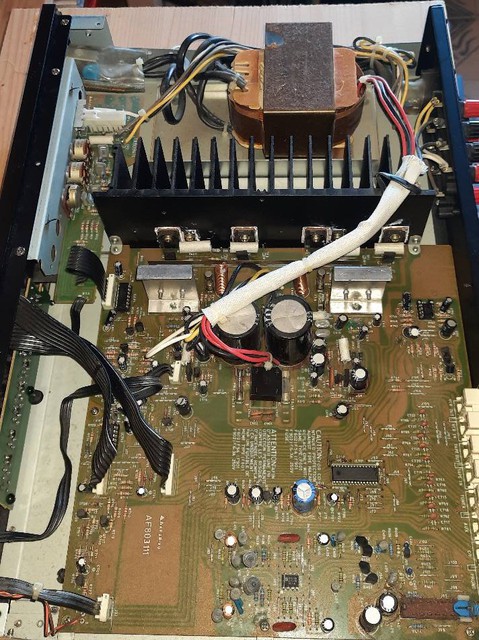 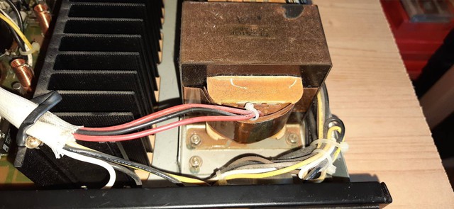 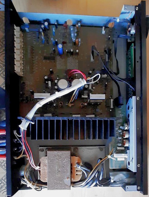 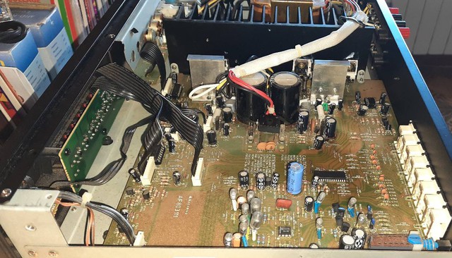 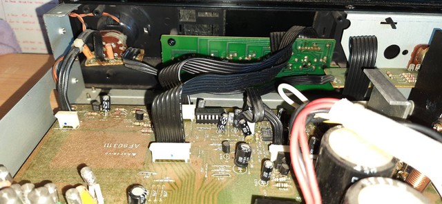 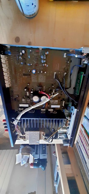 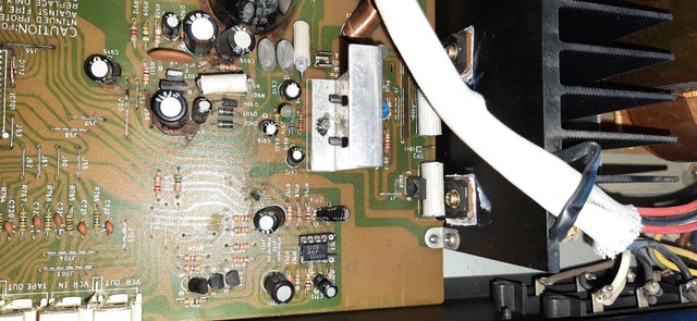 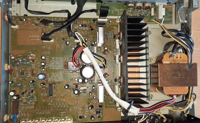 [Beitrag von CarlM. am 05. Jul 2021, 15:17 bearbeitet] |
||
|
CarlM.
Inventar |
#14
erstellt: 05. Jul 2021, 15:49
|
|
|
As we don't have a service manual you can oonly check the tensions at dedicated places. Connect the black cable of the multimeter to the chassis and check the voltages at these locations using the red cable (range: 0 .. 200 V DC): 1. output of the bridge rectifier 2. pins 4 an 8 of the DIP-8 IC (= IC in the socket with 8 pins) 3. Collectors of the big transistors located on the heat sink. But you should only do it if you are familiar with measurements. Short circuits by touching two pins at the same time will increase the problem. |
||
|
Poetry2me
Inventar |
#15
erstellt: 05. Jul 2021, 15:54
|
|
|
Auf Bild 4 erkenne ich einen öligen Fleck in der Mitte der Hauptplatine. Sehr wahrscheinlich ist der Grund ein ausgelaufener Elektrolytkondensator. Auf Bild 7 und 8 ist viel oxydierter Draht zu erkennen. Das kommt durch die Säure in dem ausgelaufenen Elektrolyt. Zuerst muss man den ausgelaufenen Elektrolytkondensator finden. Wahrscheinlich ist es einer der mittelgroßen oder kleinen Kondendensatoren neben den Leistungswiderständen, die mit Glasfaser-Schlauch umgeben sind. Diese Widerstände werden im Betrieb heiß und verursachen dadurch den Schaden an den Elektrolytkondensatoren. Hier müssen am Ende mehrere Elektrolytkondensatoren ausgewechselt werden, denn hier haben sicher mehrere Kondensatoren durch die Hitze einen Schaden. ============== english version ========= In picture 4 I see an oliy stain in the middle of the main circuit board. Most likely, the reason is a leaking electrolytic capacitor. Picture 7 and 8 show much oxydized wire. This is caused by the acid in the leaked electrolytic. First, the leaking electrolytic capacitor must be found. Probably one of the mid-sized or small capacitors beside one of the power resistors wrapped in a fibre fabric tube. These resistors get hot during operation and thereby cause damage at electrolytic caps. In the end, several of the electrolytic caps will need replacement since these can be expected to have heat damages. - Johannes [Beitrag von Poetry2me am 05. Jul 2021, 16:03 bearbeitet] |
||
|
CarlM.
Inventar |
#16
erstellt: 05. Jul 2021, 16:01
|
|
|
Das Plastik an den großen Siebelkos sieht auch nicht gut aus ... |
||
|
Antonello4923
Schaut ab und zu mal vorbei |
#17
erstellt: 05. Jul 2021, 16:03
|
|
|
I measured the voltages at the ends of the large electrolytic ocndenstaori and I have -37 vcc and + 37vcc 2. pins 4 an 8 of the DIP-8 IC (= IC in the socket with 8 pins)do you mean the one signed JRC4556D? I put the socket because I tried to replace it with a 4558 without success The ic with the sockets have already been replaced without success except the big one I didn't have a socket to mount it so I soldered it directly and new anyway about the stains it is not oil but it is the glue that placed at the base of the capacitors I checked the resistors even if they are oxidized they are ok if I solve the problem I change them all and then the capacitors |
||
|
CarlM.
Inventar |
#18
erstellt: 05. Jul 2021, 16:17
|
|
|
Yes. At the pins 4 and 8 of 4558 the voltages should be about -18V and +18V DC (range +/- 15 and 20 V). If the voltages are very low or "0 V" the power supply will be the problem. The pin layout of 4558 is shown in the datasheet: cdn-reichelt.de/documents/datenblatt/A200/NE4558%23PHI.pdf |
||
|
Antonello4923
Schaut ab und zu mal vorbei |
#19
erstellt: 05. Jul 2021, 16:21
|
|
|
pin4 measures very few variable millivolts pin8 00.6mv also variable the value does not remain fixed I made a discovery to the collectors I do not measure any voltage but there is not even at the base and at the emitter another thing on the rectifier bridge I do not measure anything but on the capacitors I have the plus and minus 37voltscc |
||
|
CarlM.
Inventar |
#20
erstellt: 05. Jul 2021, 16:31
|
|
|
You should check the connections of GND (ground). Disconnect from mains and check whether the chassis is connected to the directly connected pins of the two big capacitors. Could you make some photos of the soldering (other side of the mainboard)? |
||
|
Poetry2me
Inventar |
#21
erstellt: 05. Jul 2021, 16:33
|
|
|
I recommend that you replace all capacitors around the heat sources. As Carl already mentioned: Some electrolytic caps have visible marks from heat damage (they "undress", plastic wrap shrinks already). I marked them with a bomb symbol. 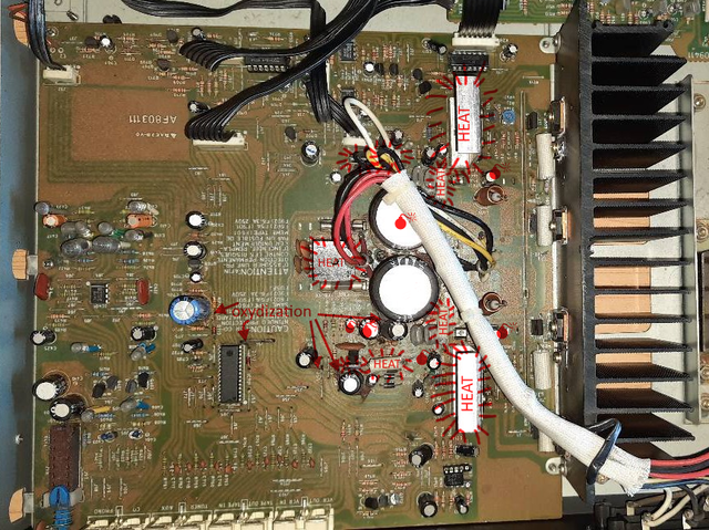 The oily stain is more than what can be caused by the glue. BTW: The glue also has acid in it and causes the same problem over the decades. Search the net for the famous "Yamaha glue". 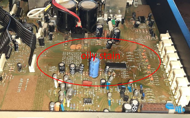 |
||
|
Antonello4923
Schaut ab und zu mal vorbei |
#22
erstellt: 05. Jul 2021, 16:37
|
|
|
With the yamaha I know I removed it from my m85 power amp a long time ago as I discovered what it could create think i had cleaned everything well and i found that there were some corroded resistances and one was also broken but the ending sounded anyway I will change the electrolytics in the points indicated let's see if it leads to something positive |
||
|
Poetry2me
Inventar |
#23
erstellt: 05. Jul 2021, 17:00
|
|
|
There you go. Also look for the green oxydization on resistors, you have some here. regarding your actual problem: I agree with Carl that most suspiciaous would be the regulators which make +15V and -15V for OpAmp supply. 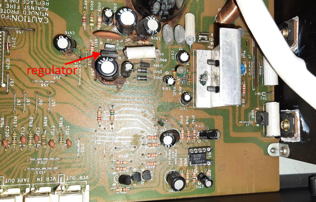 This picture shows only one of the two regulators. The other one is across the main rectifier and also has two transistors. The amp model A-03 does have something similar, and we can find the schematic for it: 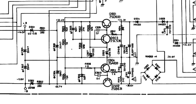 In the A-03 however, we find that the regulator's output voltage is only 2,5V lower than input. 15V levels are created behind it through in-line Zener diodes. This will be different in the A-05. I expect that in the A-05, the regulator transistor "burns down" most of the voltage drop to create the 15V, ony supported by a pre-resistor (right beside it) which burns down part of the voltage on it's way to the regulator. There are permanently a few Watts of heat created I am sure. All of the electrolytics around it will be toast.  My hunch would be that at least one of the regulator transistors has given up.  - Johannes |
||
|
Antonello4923
Schaut ab und zu mal vorbei |
#24
erstellt: 05. Jul 2021, 17:03
|
|
|
well tomorrow I dissold the regulators and put them new and I'll let you know sure how strange if a regulator burns, there is no voltage in the whole circuit? |
||
|
CarlM.
Inventar |
#25
erstellt: 05. Jul 2021, 17:30
|
|
|
... and the "POWER-LED" is supplied by the positive regulator as well ...  |
||
|
Antonello4923
Schaut ab und zu mal vorbei |
#26
erstellt: 06. Jul 2021, 10:21
|
|
|
Good morning friends so this morning I replaced the capacitors as recommended I turn on and nothing has changed then I did a test I unsoldered the two red wires and the black one and I made a measurement connecting the negative of the voltmeter to the black wire and the positive to one of the 2 red wires I have no voltage in both red wires I believe that at this point the transformer is the fault |
||
|
Poetry2me
Inventar |
#27
erstellt: 06. Jul 2021, 13:01
|
|
|
I would recommend not to turn on, before you have checked the respective transistors and diodes. There could be a short-circuit damage somewhere. For example: In case one of the rectifier diodes is shorted, you could damage your new capacitors again. Make sure you measure the secondary windings in AC mode of our multimeter. If you did so, I understand from your measurement result that the transformer has a damaged. In case the transformer has a broken thermal fuse inside the windings, this may be complicated to fix but can be done in some cases. - Johannes [Beitrag von Poetry2me am 06. Jul 2021, 13:10 bearbeitet] |
||
|
Antonello4923
Schaut ab und zu mal vorbei |
#28
erstellt: 06. Jul 2021, 13:26
|
|
|
the procedure was simple ... the owner said that this amplifier was forgotten on many days then in the end they found it with all the LEDs off and it didn't sound anymore so the first thing i did and checked fuses diodes bridge diodes transistors and they are all good..no component marks short circuit to the measure of the tester in the end this morning I wanted to disconnect the 2 red and black wires and in Ac I tried to measure them I only have very few millivolts but low bass if I have no voltage from the secondary of the transformer it is normal that the circuit is not powered at this point I leave it like this and return it to the owner |
||
| ||

|
|
||||
| Das könnte Dich auch interessieren: |
|
Onkyo A-922 klingt sehr hell Abtastfanatiker am 05.02.2015 – Letzte Antwort am 07.02.2015 – 4 Beiträge |
|
Rotel RA-05 Verstärker überhitzt / schaltet ab Dragonheart100 am 03.01.2021 – Letzte Antwort am 12.01.2021 – 6 Beiträge |
|
Pioneer PDR-05 liest keine CDs mehr ein xfekbm am 24.08.2008 – Letzte Antwort am 05.05.2015 – 20 Beiträge |
|
Elac Subwoofer 05 ESP Sicherung brennt immer wieder durch beatmastaT am 25.08.2011 – Letzte Antwort am 26.08.2011 – 3 Beiträge |
|
Amp klingt komisch, Fehlersuche wiesel77 am 30.05.2014 – Letzte Antwort am 10.02.2015 – 15 Beiträge |
|
Onkyo M5590 klingt komisch hifi-buschi am 06.12.2017 – Letzte Antwort am 08.12.2017 – 7 Beiträge |
|
Denon PMA 737 Verstärker klingt verzerrt annabsl am 06.03.2019 – Letzte Antwort am 10.03.2019 – 6 Beiträge |
|
Rechter LS klingt SEHR schlecht Inspiredfourplay am 24.01.2012 – Letzte Antwort am 24.01.2012 – 6 Beiträge |
|
T&A Power Plant Balanced links lauter hal4000 am 01.09.2017 – Letzte Antwort am 05.09.2017 – 16 Beiträge |
|
Pioneer PDR-05 knackt und öffnet den CD-Einschub nicht mehr sos am 18.09.2004 – Letzte Antwort am 11.02.2010 – 17 Beiträge |
Foren Archiv
2021
Anzeige
Top Produkte in Elektronik (Stereo&Surround)
")


Aktuelle Aktion


Partner


Top 10 Threads in Elektronik (Stereo&Surround) der letzten 7 Tage
- So repariert Ihr Euren CD-Player
- Kontaktflächen Gummimatte zb einer Fernbedienung
- Gelöst: Yamaha RX-V 2700 lässt sich nicht mehr einschalten
- PV Anlage stört auf UKW
- Verstärker rauscht
- Sony-Receiver STR-DB830: "PROTECTOR" im Display
- Yamaha RX-396 RDS schaltet sich sofort wieder aus
- CD-Fach bei Pioneer PD-5500 öffnet sich nicht
- Onkyo TX-NR 414 schaltet nicht mehr ein
- B&W Zeppelin - Netzteil/Sicherung defekt
Top 10 Threads in Elektronik (Stereo&Surround) der letzten 50 Tage
- So repariert Ihr Euren CD-Player
- Kontaktflächen Gummimatte zb einer Fernbedienung
- Gelöst: Yamaha RX-V 2700 lässt sich nicht mehr einschalten
- PV Anlage stört auf UKW
- Verstärker rauscht
- Sony-Receiver STR-DB830: "PROTECTOR" im Display
- Yamaha RX-396 RDS schaltet sich sofort wieder aus
- CD-Fach bei Pioneer PD-5500 öffnet sich nicht
- Onkyo TX-NR 414 schaltet nicht mehr ein
- B&W Zeppelin - Netzteil/Sicherung defekt
Top 10 Suchanfragen
Forumsstatistik
- Registrierte Mitglieder930.950 ( Heute: 5 )
- Neuestes MitgliedBlade_Runner_92
- Gesamtzahl an Themen1.564.231
- Gesamtzahl an Beiträgen21.847.512
