| HIFI-FORUM » Reparatur & Wartung » Hifi-Klassiker » Luxman L-210 + L -400 | |
Gehe zu Seite: |vorherige| Erste Letzte
|
|
||||
Luxman L-210 + L -400+A -A |
||
| Autor |
| |
|
Nidexx
Ist häufiger hier |
#51
erstellt: 13. Jun 2022, 09:21

|
|
|
Thank you Sir No I dont want to do that ( Full power just yet ) I have the variable transformer + light bulb after it. ( big one ) now and just a few Volts. I have yet to obtain even Voltage at both sides a and b Even if I dont get the right operating amplifier values for low Voltage.. As long as it is the same on both sides . I feel I am in a better Position. Perhaps I am Stubborn and Dumb But this being a hobby and having a learning curve. I can take it step vise . I did try the light bub 100 w and full power . Worked for a while Bulb lit up and stayed on and I later found a shorted power transistor. Darkness on LED s I did have LED s on at the circuit Board but the wrong Voltage on Q111. But had to start over again as I am doing now. Back to square one. I am thinking No power it wont fry components .Low power lesser risk . can be wrong .. But Physics and Electrics is so at times . 200 W into a 40 W Bulb Poff + darkness --40 W into a 200 W bulb :: It might not light up can still be darkness but it wont fry. I dont blame the 100 W bulb method. And I can be wrong Some transistor takes only 1.2 V on the base pin and I am applying 4.5 V already . So the plan is measure Q 112 Q 111 Q 113 Voltage on the heat sink getting those Voltages even and the same on both sides. even for low Voltage And even if they are out of spec. I believe the LED .s then come on for ca 5 V ..Then I can increase the Voltage .. still measuring Q 112 Q 111 Q 113 Transistor Voltages I have then some time to look for excessive heat somewhere touching and IR Thermometer. If I can reach operating value 45 V step vise with transformer -- With Even values on heat sink transistors both sides LED s on Evenly. I can then power down take away the transformer connect the 100 W Bulb and do the full power ON. If it fries again it can be the Electronic recycling bin a dark night. Thanks Again .Can take a while before I have the Components ( Transistor ) Perhaps measure some more on stage 3 and 4 Thanks / Jan |
||
|
Nidexx
Ist häufiger hier |
#52
erstellt: 09. Jan 2024, 16:30
|
|
|
Back at it again .Lots of other matters ,and other Old Hifi As well Not had time for a while and are taking a chance here .Sorry if it has been answered. But I believe here can be experience that can have the answer right away .Experience myself as a beginner don't have Again I apologize if these are dumb questions.And is obvious and already answered .Please have patience. Upon inspecting I noticed I had soldered out the transistor Q110b the pink in the center low 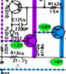 So not remembering and not having taken notes I found the transistor in the box and it was broken I do remember that the final transistors where checked and replaced soldered in place. So nothing else was missing bar that Q110b I found a replacement one that I had ordered Checked it on the cheap meter and soldered it in place .. taking a chance Soldered it in .. Connected a variable transformer and a bulb. gave it a few 10 Volts . And Voila the 2 red diodes lit up Looking inspiring good -- Left it on took measurement at the back at the final transistors legs :Overall good one leg was reading low zero i figured not yet open but Overall OK . Added more Voltage 20 V still good The control lamps on the front came up. The day after continuing Increasing Voltage .I made a mistake with the Voltmeter probe some sparks but on the other channel and Increasing voltage ca 30 V Poff one Red diode go out -- low values wrong at the final transistors After some head scratching in the head and resistance measurements the Q110b came out again and yes it was Blown / Fried again. I took a chance there .not doing more inspections before trying to power up i Reckon . I have not done much more after that one or two measurement .But thought I can put it here . Please come with thoughts which is the obvious suspect I am a beginner and Mechanical Engineer, Learning by Doing. The L-210 is in operation Best Sounding I have so far .. 4 loudspeakers connected 2 large from the 70 ies / Jan |
||
|
|
||
|
Poetry2me
Inventar |
#53
erstellt: 10. Jan 2024, 04:01
|
|
|
Too bad you had this accident during measurement. Which channel? You should now measure the parts of affected channel starting with the final stage 4 (blue) and working your way back at least to stage 2 (red). Do not forget the resistors. If one burnt through resistor remains, it will destroy all your repairs again when turning on the amp without lightbulb. 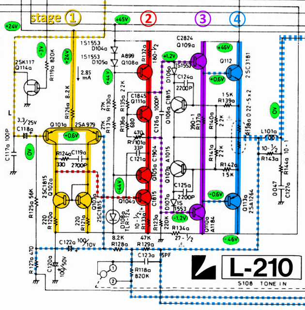 - Johannes |
||
|
Nidexx
Ist häufiger hier |
#54
erstellt: 11. Jan 2024, 02:15
|
|
|
Thank You Sir for the answer It was the b Channel going dark on the red LED Transistor fried I did measure at the output transistors on the a channel with the red diode on -- before and after .I believe that channel is still OK The sparking mishap was on the a channel but fried transistor on b The plan is to measure resistance In circuit measurements over the Transistors on the a channel and compare with the b channel se if i can notice any differences . I am thinking some other components is bad on b channel since the Transistor i Replaced was blown once before. And i Had not found it. Is in circuit measurement meaningful or do I need to take them out I have Purchased a desolderer since last time. The one fried transistor had short circuit in two directions and I took it out and put it in the Component tester found it bad. Is it the Transistors and Resistors that are the most likely to be bad ? Is there any obvious resistor on the transistor input that makes it fry Perhaps replace without thinking If it is a power dependent fault Thank you again for kind help Appreciate It / Jan |
||
|
Poetry2me
Inventar |
#55
erstellt: 11. Jan 2024, 03:29
|
|
|
It would be easier if you coud precisely name the affected parts where the spark happened and also which LED went out. Was the LED D108b ??? L-210 has only one LED per power amp channel. If this LED goes out, there must be a damage in stage 2. As I have said before: Rarely is the damage only in transistors. Most of the time you will also find damaged resistors and sometimes diodes etc. Check all resistors and diodes of the stages 2 - 4. After replacement of damaged parts you may carefully start the amp again but ALWAYS with a lightbulb 60W looped in instead of the primary side fuse. Then try to measure the voltages along the colored rail-to-rail DC path in each stage. Note down your measured values and post everything here. - Johannes |
||
|
Nidexx
Ist häufiger hier |
#56
erstellt: 15. Jan 2024, 01:12
|
|
|
Thank you Sir Luxman 400 This evening I had some more time to measure more accurately. It is the channel b that has gone bad And it was the LED D108b that went out. Q 110 b is destroyed is out. Q 106 b is also destroyed tester showed that on in circuit measurement Q 106 a Showed OK same measurement setup and I soldered out Q 106 b and is Bad. Q111 Q112 Q113 seems OK as far as my cheap component tester Shows Both channels No Fuse was open I have measured close to Q 110 b cant find anything will go over it again before Power up Not yet measured downstream from Q 106 b some resistors there Se if I can get hold of transistors can take a while / Jan |
||
|
Nidexx
Ist häufiger hier |
#57
erstellt: 15. Jan 2024, 21:54
|
|
|
Soldered in 2 Transistors Was not able to find any bad resistor both Red LED .s came up for small Voltage . Variable transformer + have Bulb Will make small Probes so I have a better chance measuring not getting sparks |
||
|
Poetry2me
Inventar |
#58
erstellt: 16. Jan 2024, 02:56
|
|
|
When making measurements using the lightbulb, be aware that rail voltages will be lower than +/-48V, for instance something like +/-39V. What really counts: 1. Amp output voltage should max be at a two-digit Millivolts level. 2. You should be able to measure Base voltages at the final transistors (+/-0.6V) and Base voltages at the driver transistors (+/-1.2V or slightly less). Then you know the amplifier is likely to function in principle. Next would be to determine the idle current. This can be done by a) measuring the voltage drop between the ends of one Emitter resistor (e.g. one half of R138b) and b) use Ohm's Law to calculate the resulting idle current running rail-to-rail through this stage. For instance 3.3mV across one Emitter resistor indicates an idel current of 15mA I = U / R = 0.0033V / 0.22Ω = 0.015A = 15mA; |
||
|
Poetry2me
Inventar |
#59
erstellt: 15. Apr 2024, 20:00
|
|
|
I am curious if you could make some progress? - Johannes |
||
|
Nidexx
Ist häufiger hier |
#60
erstellt: 16. Apr 2024, 22:39
|
|
|
Thank You for the interest .. I have not had time because of legal problems . 2 Estates property division. |
||
| ||

|
|
||||
Gehe zu Seite: |vorherige| Erste Letzte
| Das könnte Dich auch interessieren: |
|
Luxman L 210 Problem! *Blackbeard616* am 13.03.2009 – Letzte Antwort am 16.03.2009 – 7 Beiträge |
|
Luxman L-210 Sholva am 15.06.2013 – Letzte Antwort am 17.06.2013 – 14 Beiträge |
|
Luxman L 210 Problem Homer_69 am 14.12.2021 – Letzte Antwort am 07.04.2023 – 49 Beiträge |
|
Luxman- L 400 ohne Musikleistung Schissi am 14.11.2016 – Letzte Antwort am 15.11.2016 – 6 Beiträge |
|
Luxman L-210, mal wieder was "Neues" blademage am 25.08.2020 – Letzte Antwort am 02.11.2020 – 35 Beiträge |
|
Luxman L-113A Homer_69 am 03.04.2022 – Letzte Antwort am 08.04.2022 – 13 Beiträge |
|
Luxman L-400 Birnen wechseln - alle tot toddrundgren am 07.08.2013 – Letzte Antwort am 08.08.2013 – 2 Beiträge |
|
Luxman L-410 defekt motoerhead68 am 30.12.2004 – Letzte Antwort am 04.01.2005 – 14 Beiträge |
|
Luxman L-410 Ruhestrom woz am 02.10.2007 – Letzte Antwort am 03.10.2007 – 4 Beiträge |
|
Luxman L-410 Aussetzer earny22 am 18.02.2008 – Letzte Antwort am 09.03.2008 – 6 Beiträge |
Anzeige
Produkte in diesem Thread


Aktuelle Aktion


Partner


Top 10 Threads in Hifi-Klassiker der letzten 7 Tage
- Kondensator ersetzen mit höherem Wert - zulässig?
- WD40 als Kontaktspray?
- Grundig R-2000 Mutingproblem
- Entstörkondensator- Beschriftung und deren Bedeutung
- Dreh - Lautstärkeregler defekt? reagiert falsch oder gar nicht Aiwa NSX AV 320
- Problem bei Reparatur von Pioneer CT 676
- Marantz / Superscope CD-302A Tape Deck
- "Tapedeck-Reparatur" Thread
- Welche Glassicherungen/Feinsicherungen Flink oder Träge ?
- Akai GX-260D-Überholung, Transistorersatztypen?
Top 10 Threads in Hifi-Klassiker der letzten 50 Tage
- Kondensator ersetzen mit höherem Wert - zulässig?
- WD40 als Kontaktspray?
- Grundig R-2000 Mutingproblem
- Entstörkondensator- Beschriftung und deren Bedeutung
- Dreh - Lautstärkeregler defekt? reagiert falsch oder gar nicht Aiwa NSX AV 320
- Problem bei Reparatur von Pioneer CT 676
- Marantz / Superscope CD-302A Tape Deck
- "Tapedeck-Reparatur" Thread
- Welche Glassicherungen/Feinsicherungen Flink oder Träge ?
- Akai GX-260D-Überholung, Transistorersatztypen?
Top 10 Suchanfragen
Forumsstatistik
- Registrierte Mitglieder931.209 ( Heute: 2 )
- Neuestes MitgliedZap_Dev
- Gesamtzahl an Themen1.564.973
- Gesamtzahl an Beiträgen21.873.508
