| HIFI-FORUM » Reparatur & Wartung » Hifi-Klassiker » Luxman L-210 + L -400 | |
|
|
||||
Luxman L-210 + L -400+A -A |
||
| Autor |
| |
|
Nidexx
Ist häufiger hier |
#1
erstellt: 01. Nov 2020, 14:32

|
|
|
Hallo Ang Luxman L-210 Luxman L-400 Bitte um Entschuldigung für der Sprache. Ich lebe in Süd Schweden und versuche es mit Schule Deutsch und Internet Übersetzung Ich kann nicht viel von Elektronik. Oder HiFi . Aber seit 35 Jahren Fehler Finden bei Motorrädern. Und interessiert mich für Musik mit Instrumenten. Daher bin ich der Meinung, dass der L-210 gut ist und es sich lohnt, Reparieren . Kaufte es gebraucht . Aber der Sound war gut. Ich habe es ein paar Jahre lang benutzt, aber dann hat es aufgehört zu funktionieren Aktuelle Situation L-210 Der Ton ist schwach und auf beiden Kanälen verzerrt. Wenn Sie Volumen an 1/2 von Max oder mehr ziehen, hören Sie den Ton von einem CD-Player. In angeschlossenen Lautsprechern. Aber im normalen Gebrauch, bevor der Fehler auftrat, hatte ich wahrscheinlich nie mehr als 1/4 des Volumen . Es brennen keine Sicherungen Die Zenerdiode d112 ist ersetzt und komplett. Beide LED- Dioden auf der Leiterplatte sind rot. Ich habe versucht, auf der Leiterplatte zu messen, finde aber nichts falsch. Ich fange an zu vermuten, dass es sich um einen Kondensator handelt, der nicht mehr funktioniert. Ich möchte nicht alle ersetzen , weil der Sound vor dem Fehler gut war: Idealerweise wollte ich nur einen oder mehrere davon ersetzen, Kann es so sein ? Wäre dankbar für Tipps L-400 Beim Einschalten der Spannung brennt eine seitliche Sicherung. Ich habe Kondensatoren darauf ersetzt. Ich denke, es hat einen Transistor Fehler Ausgang.. Und vielleicht noch mehr. Noch nicht viel debuggt Schwieriger natürlich, aber manchmal gibt es Experten für diese Art Fehler am Forum. Diese weisen direkt auf den wahrscheinlichsten Fehler hin. So ist es mit Motorrädern. Wäre auch dort für Tipps dankbar mfg Jan. |
||
|
Ingor
Inventar |
#2
erstellt: 01. Nov 2020, 19:58
|
|
|
Warum hast du die Zenerdiode ausgetauscht? Hast du den Schaltplan (service manual)? Wenn nicht: https://elektrotanya.com/luxman_l-210_sch.pdf/download.html#dlHast du zum Test mal ein Signal hinter dem Umschalter angelegt? Also an A5 Vor dem Lautstärkeregler? Stimmen alle Spannungen? |
||
|
|
||
|
Nidexx
Ist häufiger hier |
#3
erstellt: 01. Nov 2020, 21:57
|
|
|
Vielen Dank für Antwort Zenerdiode war kaputt Ich habe Schaltplan Ich habe nicht eine signal hinter A5 angelegt Wie tut man dass ? Ich glaube dass Spannungen stimmt es gibt viele messpunkte und die ich gemessen hat is OK Ich kann es noch einmal eingehend tun --falls Wichtig ist . so ich bin sicher sämtliche is OK Es war voriges winter ich versuchte.Und Notizen ist nicht gut. mfg Jan |
||
|
Ingor
Inventar |
#4
erstellt: 02. Nov 2020, 01:20
|
|
|
Schließe den CD Player an Aux an. Verbinde A1 mit A5. Es reicht ein Draht linker Kanal an A1 nach linker Kanal A5. |
||
|
Poetry2me
Inventar |
#5
erstellt: 02. Nov 2020, 01:53
|
|
|
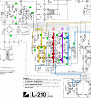
Hallo Nidexx, Wenn ich Dich richtig verstehe, dann ist der Fehler auf beiden Kanälen gleich. Das heißt, dass der Fehler wahrscheinlich in der Stromversorgung liegt. Hast Du den anderen Thread gesehen, der vor kurzer Zeit hier im Forum eine L-210 Reparatur beschreibt? http://www.hifi-foru...d=17386&postID=16#16Auf dem Schaltplan mit farblich markierten Schaltungsstufen findest Du links oben die Spannungsregler, welche 24V und 46V für die ersten zwei Stufen erzeugen. Diese Spannungen werden von beiden Kanälen verwendet. Prüfe sie am besten. Teste auch, ob das Problem genauso stark ist, wenn Du mit Kopfhörer hörst. Wenn nein, dann kann das interessante Hinweise für die Diagnose liefern. Etwas kann eventuell nicht genügend Strom an die Lautsprecher liefern. In dem anderen Thread gibt es auch einen Tipp, welche Elektrolyt-Kondensatoren in der Gegenkopplung Probleme machen können. Diese altern stark, weil sie geringere Spannung haben. http://www.hifi-foru...d=17386&postID=20#20- Johannes [Beitrag von Poetry2me am 02. Nov 2020, 02:02 bearbeitet] |
||
|
Nidexx
Ist häufiger hier |
#6
erstellt: 02. Nov 2020, 02:30
|
|
|
Danke für Antwort Ich Habe nicht andere thread gesehen ich soll lesen und messen Auch das tun Schließe den CD Player an Aux an. Verbinde A1 mit A5. Es reicht ein Draht linker Kanal an A1 nach linker Kanal A5. Es kann ein par tagen dauern mfg Jan |
||
|
Nidexx
Ist häufiger hier |
#7
erstellt: 03. Nov 2020, 06:32
|
|
|
Hallo Hallo die Situation Habe ein bisschen gemessen und A5 und A1 und angeschlossen Versuchte mit Kopfhörern Herausgenommen C122 a, b C201a C204b (nicht b resp a wird benötigt?) Verbinden. A5 und A1 gaben eine deutliche Lautstärkeerhöhung an --- Signifikant ..Aber immer noch mit verzerrtem, schlechtem Klang ( Ich habe kabel am Lötpunkten gehalten .. nicht getrennt ) Mit Kopfhörern Die gleichen schlechten verzerrten Klänge, wie ich rechts und links genauso schlecht erlebe Balance wirkt. Gemessen ohne angeschlossene Lautsprecher Spannung an den Sicherungen +/- 47,4 V (bei angeschlossenem Lautsprecher 48 V) Stufe 1 +24,5 V vor R126 a b 0,67 danach Stufe 2 an Diode D104 a, b . 46.7 46.0 Stufe 3 an der Diode D106 a, b 1,1 V 0,09 Ich habe ein bisschen auf der Minus-Seite unten im Schaltplan gemessen. Kann nicht etwas Fehler sehen bitte sagen , ob es interessante Punkte gibt. Ich habe ein billiges Komponentenmessgerät, ca 10 Euro mit dem ich Komponenten teste Es zeigt 5308 nF für Kondensator C201a Soll 4,7 üF 25 V. Sein http://www.hifi-foru...d=17386&postID=20#20Könnte das der Fehler sein? mfg Jan |
||
|
Poetry2me
Inventar |
#8
erstellt: 03. Nov 2020, 21:20
|
|
|
Ich empfehle, die Spannungen an allen Punkten in der Verstärkerschaltung zu messen. 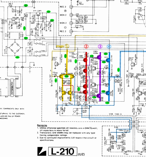 [Beitrag von Poetry2me am 03. Nov 2020, 22:17 bearbeitet] |
||
|
Poetry2me
Inventar |
#9
erstellt: 03. Nov 2020, 21:54
|
|
|
||
|
Nidexx
Ist häufiger hier |
#10
erstellt: 04. Nov 2020, 04:35
|
|
|
Hallo Und Danke Scheint in die richtige Richtung zu gehen. Vielleicht hatte Ingor etwas in seinem Vorschlag, A5 mit A1 zu verbinden Kondensatoren austauschen ======> 5308nF = 5,3µF (sollte haben: 47,0µF). Eine zu kleine Kapazität kann eigentlich nur den Bass begrenzen. Der Kondensator C201a ist jedoch definitiv verdächtig und muss ersetzt werden. ------> Kein Unterschied. Dann bemerkte ich das, als ich den Funktionsknopf zwischen Tuner / Aux / DAD / Phono drehte Phono Subsonic . Es brüllte laut, als es in die Positionen gedreht wurde, in denen nichts angeschlossen ist Da stimmt etwas nicht. Nur angeschlossen ist CD-Player unter Aux Abgeschraubt versuchte es zu reinigen, weiß aber nicht genau, wie man es tun . Sieht nicht so aus, als ob es geöffnet werden kann. Verwenden Sie Alkohol oder Lösungsmittel. ? --- nimmt dankbar Vorschläge Ich habe Kontaktspray verwendet Nachdem die Volumen besser funktioniert hat, werden etwa 25% des Maximums benötigt. Wahrscheinlich das gleiche wie zuvor, als es funktionierte. Während vor dem Kontaktspray wurden ca. 60% benötigt. Wenn Funktionsknopf an Phono dreht , brüllte es -- aber weniger. Der Klang ist immer noch schlecht mit zu vielen Diskant , aber bei Kopfhörern ist er besser. Dort fehlt ein Kanal. Balance funktioniert nicht . Wenn Sie ihn nach rechts drehen, wird er leise. Aber ich habe das schon mal bei einem anderen Luxman gesehen, einem R-404 R-404 der Grund war, warum ich danach 3 andere hatte. Dort verschwand der Sound in einem Kanal und fehler befand sich im Balance-Regler. Dann denke ich, dass es wieder dasselbe ist. Daher denke ich im Moment, dass das Reinigen von Schaltern der erste Schritt ist. Was verwenden Sie, um dies zu tun, oder sollten man auf irgendeine Weise Bypass oder den Kontakt wechseln? Oder gibt es Komponenten. ( kapazitansen ? ) Ich habe noch keine anderen Messpunkte gemessen. Da der Volumen zuruck kam , Trotz schlecht , dachte ich, ich würde das Gerät eine Weile ( über nacht ) stehen lassen, damit Kondensatoren, die möglicherweise etwas zu alt sind, wieder aufgeladen werden können. Danach messe ich bei Bedarf andere Messpunkte . mfg und Danke Jan |
||
|
Nidexx
Ist häufiger hier |
#11
erstellt: 04. Nov 2020, 09:01
|
|
|
Hallo Ich habe ein Spannungs Fehler gefunden Lampe wirkt nicht glaube kaputt R 153 haben beide seiten -22.9 V und -35.5 V soll -40 sein R 149 haben beide seiten 46.9 V und 0.09 kalt power up .. bis -0.15 V warm soll -3 sein - 3 V geht zu Q 114 und bekomme Volumen und Balance Signal. mfg Jan |
||
|
Poetry2me
Inventar |
#12
erstellt: 04. Nov 2020, 20:20
|
|
|
Ja, da ist wahrscheinlich ein Fehler. In einem anderen Thread zum Luxman L-215 habe ich mal analysiert, wie die Schaltung funktioniert. Über die beiden Dioden D113 und D114 wird separat eine negative Spannung -40V erzeugt, Diese versorgt die Lampen und liefert eine negative Vorspannung für einen Muting- und Slow-Start-Mechanismus (Anti-Plopp-Sound). Die Lampenspannung wird noch mal mit Widerstand R153 und Zenerdiode D112 heruntergezogen auf -22V. Diese heiße Diode und der Widerstand sind Schwachstellen und häufig defekt. Der Slow-Start-Mechanismus wirkt nach dem Einschalten und erzeugt eine Spannung von -3V. Diese Spannung geht zum Gate der JFET Muting-Transistoren an den Endstufen-Eingängen. Dadurch wird der JFET Transistor hochohmig und die Muting-Funktion wird deaktiviert. Die -3V werden durch eine Balance zwischen den Versorgungsspannungen +46V und -40V über die Widerstände R148 und R150 erzeugt. Wenn die -3V Spannung bei Deinem Gerät nicht mehr -3V ist sondern in der Nähe von Null Volt, dann könnten die FET Transistoren teilweise schon niederohmig werden und die Mute-Funktion in einem Zwischenzustanf hängen. Die Zenerdiopden und Elkos in diesem Schaltungsteil sind eine bereits bekannte Schwachstelle an allen Luxman L-190, L-205, L-210, L-215, L-220, L-225, L-230, L-235, L-400 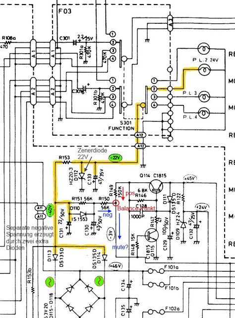 Man muss alle Zenerdioden und Brat-Widerstände dort prüfen und ersetzen. Elektrolytkondensatoren, welche viele Jahre lang in der Hitze der Z-Dioden und Brat-Widerstände gegrillt worden sind, müssen getauscht werden. Einige Lötstellen können durch die Hitze schlecht geworden sein. Ich habe schon einmal den Vorschlag gemacht, zusätzliche Bohrungen in die Platine zu machen, um bessere Konvektion zu bekommen. 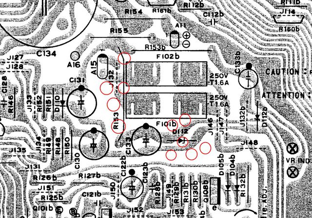 - Johannes |
||
|
Ingor
Inventar |
#13
erstellt: 04. Nov 2020, 21:36
|
|
|
Johannes, mach die Sätze nicht zu kompliziert und verwende keine Worte wie "Bratwiderstände". Der TE übersetzt das mit Google. |
||
|
Nidexx
Ist häufiger hier |
#14
erstellt: 05. Nov 2020, 04:41
|
|
|
Hallo und danke Begann mit Auslöten und Ersetzen von Kondensatoren usw. und sah , dass R 153 mehr oder weniger nicht gelötet war Auf der einen Seite Nach dem fest Löten habe ich die Spannung an R119a und R119b auf ca. -2,75 V gebracht Ich denke, die Verzerrung ist verschwunden Aber Bass fehlt noch. Wenn ich den Balance-Knopf nach rechts drehe, verschwindet der Ton. Aber ich kann ihn in beiden Seiten Kopfhörern schwach hören. Wenn ich nach links drehe, kommen beide Kanäle und wenn Knopf sich links vom Mittelpunkt befinden, werden beide gleich stark und bleiben so. Ich muss ein wenig nachdenken und die Tipps durchlesen, noch ein mal spannungen messen. C 122 a und C122 b können sich auf diese Änderungen auswirken, aber ich habe keine zu hause und muss bestellen. Bitte , Vorschläge , wenn es offensichtliche Dinge gibt, die zuerst überprüft werden müssen. Ich habe in der Schule Deutsch gelernt, . Ein wenig verstehe ich . Und dies ist technisch-wissenschaftlicher Natur, Ich bin dankbar für die Hilfe , Ich hatte das nie geschafft mfg Jan |
||
|
Poetry2me
Inventar |
#15
erstellt: 05. Nov 2020, 19:46
|
|
|
Sehr gut! Einen Teil der Probleme hast Du schon gefunden denke ich. Ich sehe es so wie Du. Als erstes müssen die Elektrolytkondensatoren in dem ganzen Bereich OK sein. Dann kann man sehen, ob noch weitere Probleme existieren. Hitze ist einer der Hauptgründe für Schäden an HiFi-Geräten. Und bei der Serie L-190 / L-2xx / L-400 findet man weitgehend die selbe Schaltung mit den selbem Schwachstellen durch Hitze. - Johannes [Beitrag von Poetry2me am 05. Nov 2020, 19:46 bearbeitet] |
||
|
Nidexx
Ist häufiger hier |
#16
erstellt: 09. Apr 2022, 13:30
|
|
|
Meine Herren Nochmals maschinelle Übersetzung und Entschuldigung für den Fehler. Nach einer Weile habe ich gelesen + gelötet + geändert. Denken Es gab einige Fehler Ich bin noch ein Anfänger, habe aber ein paar Punkte, die anderen helfen könnten Zusätzlich zu Hilfe oben habe ich ..häufige Fehler wie oben erhalten. Einige Transistoren defekt hatte auch ein R134a unterbrochen Selbst ein Kurzschluss des FET Q114a konnte nicht balance einstellen. Für die Fehlerbehebung kann Folgendes ein Weg weiter sein Reinigen Sie die Bedienelemente mit Deoxidation Es wird sichergestellt, dass beide Seiten die richtige Versorgungsspannung von Q 114 und Umgebung haben Dann gibt es 2 LEDs D108 zwischen Stufe 1 und 2 Wenn Sie einen Drehtransformator verwenden, leuchten diese LEDs bei niedrigen Spannungen und beide müssen gleichermaßen leuchten Andernfalls werden Spannungen zwischen den verschiedenen Seiten auf Differenzen gemessen.+ Korrigiert Ich habe einen (billigen) Komponententester von e-bay verwendet. + Voltmeter Ausgangstransistoren habe ich günstig bei e-bay gekauft.. Dort bin ich für Meinungen dankbar Teilweise wird gemunkelt, dass es qualitativ schlechter sein könnte und teilweise habe ich den Fehler gemacht, zu grosse transistoren einlöten In der Komponentenliste wurde eine kleinere Größe angegeben als im Schaltplan angegeben Ich hatte Zugang zu. Ich habe 2SC 3181 / 2SA1264 eingelötet, aber in der Komponentenliste sind sie kleiner 2SC3180 / 2SA1263 Da könnte ich mir jetzt im Nachhinein die defekte Ausgelötete Transistoren anschauen Nachdenken über Veränderung. Könnte dies den Klang beeinflusst haben? Es klingt gut:. Aber für mich hat es vorher noch besser geklungen. Klingt etwas mehr Bass und abgesenkte Höhen. Ist der Eindruck. Aber es ist lange her, dass ich damit angefangen habe. Und hat viela andere HiFI gehört in Zwishenzeit. Das könnte falsch sein. Wäre dankbar für Vorschläge zu geeigneten günstigen Lautsprechern. Danke für Hilfe / Jan_P |
||
|
Poetry2me
Inventar |
#17
erstellt: 09. Apr 2022, 19:46
|
|
|
@Nidexx: ____GRATULATION____ zur erfolgreichen Reparatur!  Die Übersetzung funktioniert gut  Es gab viele Fehler im Gerät: Respekt! Wenn Du das vorher noch nicht gemacht hast, dann hast Du wirklich gut gearbeitet. Transistoren Q114a/b: Die Transistoren Q114a/b sind JFET Transistoren am Eingang jeder Endstufe und haben eine "Mute" Funktion. Durch Ansteuerung des Q114a/b wird das Eingangssignal für den Kanal auf Masse gezogen. Die Ein-Steuerung der Mute Transistoren wird über eine Verzögerung der Aufladung von Kondensator C130 gemacht. So wird erst einige Sekunden nach dem Einschalten des Gerätes Mute ausgeschaltet. Reinigung der Schalter und Regler: Das ist der richtige Weg, denn die Schalter und Regler spielen bei vielen Fehlern eine Rolle. Man muss es nach über 40 Jahren eigentlich immer empfehlen. Leuchtdioden D108a/b: Alle LED auf der Hauptplatine haben die Aufgabe einer Konstant-Spannungsquelle von ca. 1,9V (wieviel exakt?) zu dienen. Damit werden die Basisanschlüsse der Konstant-Stromquelle Q108a/b und der Cascode Q104a/b auf einer festen Spannung gehalten. Wenn eine dieser LED defekt ist, kann die Schaltung auch nicht funktionieren. Die Idee, mit einem Stelltrafo langsam hochzufahren und dabei die LED zu beobachten finde ich sehr gut. Defekter Widerstand R134a: Dann hat für die linke Endstufe die negative Railspannung bei den ersten beiden Stufen gefehlt. Das ist ein ernsthafter Fehler und etwas ungewöhnlicher. Billiger Komponenten-Tester: Ich denke diese preiswerten kleinen Test-Geräte (13 auf ebay) sind genial. Damit hat man wesentlich mehr Information über die Bauteile, auch wenn die Messwerte ungenau sind. Billige Leistungstransistoren / Fake: Das ist immer wieder ein Problem, das wir mit Reparaturen habe, vor allem mit Leistungstransistoren (100W..150W) und den Treibertransistoren (2W..20W). Manchmal auch mit kleineren Typen. Wir kennen auch große deutsche Elektronik-Versand Firmen, die keine Qualitätskontrolle durchführen bzw. offensichtlich immer aus der billigsten Quelle kaufen und dann bei einigen Halbleitern schlechte Qualität liefern. ebay ist praktisch immer ein Problem, das ist nicht zu empfehlen. Auch wenn die Beschreibung der Produkte wunderbar aussieht. Man muss bei Elektronik-Versand Firmen kaufen, welche die Ware direkt von den Herstellern beziehen und auch Rüstung und Raumfahrt beliefern. Beispielsweise Mouser und Digikey. Ersatztypen für die Leistungstransistoren: Die genannten Leistungstransistoren sind alle im Prinzip OK und auch nicht der Grund für Klang-Unterschiede. Zum Beispiel sind die Typen 2SC3180, 2SC3181, 2SC3182 (und die Komplementär-Typen) alle in der selben Produkt-Linie von Toshiba gewesen und haben ähnliche Eigenschaften. Aber die Maximalwerte für Spannung (Volt) und Strom (Ampere) dieser Transistoren sind jeweils unterschiedlich: 2SC3180: 80V 6A 2SC3181: 120V 8A 2SC3182: 140V 10A Für den Luxman L-210 genügen nur die letzten beiden Typen, da die Maximalspannung größer sein muss als die Summe der Rail-Spannungen im Verstärker, also 2 * 46V = 92V; Dazu kommt, dass diese Transistoren (glaube ich) nicht mehr gefertigt werden. Was man heute kaufen kann, ist mit größerer Wahrscheinlichkeit Fake. Man muss Ersatz anders suchen: Es muss ein Transistor-Typ sein, der aus aktueller Produktion kommt und über einen sicheren Versand-Partner gekauft werden kann. Ein Beispiel habe ich hier bei einem Yamaha A1020 bzw. Luxman L-410 Thema diskutiert: http://www.hifi-foru...=9578&postID=105#105In beiden Amps ist 2SC3182 (und Komplementär-Typ) im Einsatz. Der Alternative Typ kommt vom amerikanischn Hersteller ONSEMI / Fairchild und wird von Mouser, Digikey, Farnell direkt vom Hersteller bezogen.
Diese Transistoren würde ich nehmen, wenn es wirklich ein andere sein müssen. Klang ist jetzt anders als vorher: Ich würde erst einmal alles einpielen lassen. Gerade die Kondensatoren brauchen mehrere Tage oder manchmal ein paar Wochen. Die ersten Stunden nach dem Einschalten sind oft schlimm. Mache Dir erst mal noch keine Sorgen, alles wird gut.  - Johannes |
||
|
Nidexx
Ist häufiger hier |
#18
erstellt: 09. Apr 2022, 23:49
|
|
|
Vielen Dank hervorragende Informationen / Jan_P |
||
|
Nidexx
Ist häufiger hier |
#19
erstellt: 01. Jun 2022, 13:22
|
|
|
Maschinelle Übersetzung sorry Luxman L-210 läuft .. klingt gut Habe versucht, den L-400 zu reparieren Ein paar (Anfänger-) Fehler, die anderen helfen könnten Habe mit dem Lötkolben das Kupfer am Platine zerstört, als ich versuchte komponente herauszulöten Erwägen den Kauf von Aus Lötgeräten, Kurzschluss mit dem Voltmeter, als ich spät in der Nacht die Spannung an einem Transistor gemessen habe. Nicht gut Dünnere Messspitzen hergestellt, die bis zur äußersten Spitze isoliert sind Die roten Dioden des L-400 leuchten jetzt für 4 - 5 V sieht richtich aus. Aber wenn ich den Drehtransformator erhöhen , steigt die Spannung um -1,2 V In Q110a also bei ca. 9 V am Drehtransformator ist es 1,35 V Wage es nicht, weiter zu Drehen Wäre dankbar für Informationen zu wahrscheinlichen Ursachen. Die Dioden sind soweit ich sehen kann OK ( D106a D07a ) DANKE / Jan werde wohl noch eine weile bei dieser marke bleiben Tipps für den nächsten Schritt werden dankbar entgegengenommen Preis / Leistung gunstig ohne zu teuer zu sein  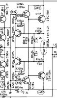 |
||
|
CarlM.
Inventar |
#20
erstellt: 01. Jun 2022, 17:13
|
|
|
Hello Jan, the translation is not as good as it should be. Perhaps you can repeat your posting by using your native language. Please try to be very precisely. "Drehtransformator" means "bias potentiometer"? Carl |
||
|
Nidexx
Ist häufiger hier |
#21
erstellt: 01. Jun 2022, 18:18
|
|
|
Thank You Sir Trying in English ..I am better on that I am a Newbie .. So feel free to assume I don't know the first basic things. I had 2 Luxman one is repaired L-210 the other L-400 is on the desk and I have an issue with it now that perhaps someone more skilled can explain. I made a few beginners mistake on the 400 using to much heat on the circuit board traces + Shorted a transistor ..with the Voltmeter. Fixed Now as far as I know. On these Luxman there is 2 Red / 1 per side LED that is indicating that the first stage OK D108 a at lower left and the same on the other side D 108 b Please look at the first post with the substandard translation 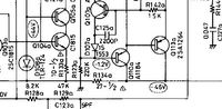 So after the repair i use a Variable transformer to stepwise power up the amplifier This to prevent it from blow the transistors again .Should something go / be wrong .And making it possible to take some measurements in the circuit. Looks like that 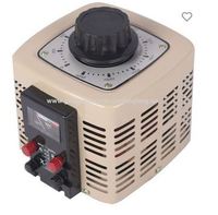 So on powering up the LED s come on at 4 -5 V .. I raise some more everything seems fine power up to 9 V Taking measurement on the transistors on the backside The ones attached to the heatsink And are finding differences on transistor Q 111 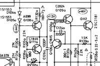 I then measure over the Diodes D107 a b Should be -1.2 V One side is low as expected for 9 V power in -- ( 45 V is operating Voltage ) the other side rises over -1.2 to -1.35 for 9 V Where I stop increasing Voltage on the variac ,,Trying to figure out the reason. Before increase Voltage Thank You for the response Please come back if this needs further clarification I find it difficult to find what component it is causing the effect .But giving it a try here. Not knowing if it is difficult for everyone. Or is 9 V just to low Voltage applied ..Trying to avoid that blue smoke in the room / Jan |
||
|
Poetry2me
Inventar |
#22
erstellt: 01. Jun 2022, 18:23
|
|
|
Meine Interpretation: Mit "Drehtransformator" ist hier ein echter Stell-Transformator (wahrscheinlich in Spar-Schaltung) gemeint. EDIT: Er hat geantwortet. Ich lag richtig. |
||
|
Poetry2me
Inventar |
#23
erstellt: 01. Jun 2022, 18:29
|
|
|
@Jan: Did we already recommend the "Light Bulb Trick" ? It works much much beter than your transformer. basically, what ist does is provide a current limitation when turning on the device. It protects your parts and transistors from burning through again by restricting current flow on the primary side of the transformer. What you need to do is find an old school light bulb of 100W (or 2 x 60W in parallel) and replace the primary fuse with the lightbulb. |
||
|
Poetry2me
Inventar |
#24
erstellt: 01. Jun 2022, 18:32
|
|
|
With the lightbulb in, you may turn on just like normal and then do your measurements without destroying anything. Your transformer will not protect anything, it is by far not fast enough when current suddenly rises. |
||
|
Poetry2me
Inventar |
#25
erstellt: 01. Jun 2022, 18:37
|
|
|
Again: The LED are not indicators !!! These are critical components to set internal voltages to certain levels. I do not understand what exactly you are measuring in wich position. Try using lighbulbs ant turn on normally. Te lightbulb should light up for 3 to 6 seconds then fade down to a low shimmering. Then do your measurements. [Beitrag von Poetry2me am 01. Jun 2022, 18:37 bearbeitet] |
||
|
Poetry2me
Inventar |
#26
erstellt: 01. Jun 2022, 18:44
|
|
|
L-400 and L-210 share almost the same schematic and PCB layout. You can use what you have from your L-210 repair. Begin you measurements by checking the green voltages in the schematic I provided above, starting from stage 4 (blue) and working your way backwards through the stages. Each stage has it's own quiescent current flowing along the (colored) DC path from +rail to -rail.
In this schematic, I have calculated missing voltages and added them in. - Poetry2me [Beitrag von Poetry2me am 01. Jun 2022, 18:47 bearbeitet] |
||
|
Poetry2me
Inventar |
#27
erstellt: 01. Jun 2022, 18:54
|
|
|
This Luxman L-205 PCB layout may help you locating the transistors of the different stages (marked in the same colors as in the schematic) on your PCB: 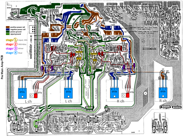 - Johannes |
||
|
Nidexx
Ist häufiger hier |
#28
erstellt: 01. Jun 2022, 19:40
|
|
|
Thank You Sir I have a 500 W Photo Lamp bulb in series after the transformer Before the Amplifier I shall check the wiring on that and check and think on the other answers here Perhaps later today. the extra calculated Voltages will help The Voltage I am suspicious of -1.2 V inside the Oval is already -1.35 for only 9 V on the fuses Afraid that full Voltage applied will destroy something Thanks Again Jan is 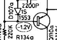 |
||
|
Poetry2me
Inventar |
#29
erstellt: 01. Jun 2022, 22:39
|
|
|
I think I understand your worries about the -1.35V where there should be -1.2V. But all is good. You should know that the quiescent current transistor Q111a is wired to be a constant voltage source which is supposed to keep 2.4V between it's Collector and Emitter. It will maintain this voltage as soon as it has enough voltage to operate. This sort of one-transistor-circuit is called "Vbe Multiplier". It will drift up and down with the signal and will always iave roughly 2.4V. So if you measure something different there, better check between Q111a Collector and Emitter if it has the 2.4V. If it drifts up or down, some of the other transistors of stage 3 (violet) and stage 4 (blue) are likely to be faulty. That's why I recommend to "follow the protocol": Start measuring from stage 4 (blue). |
||
|
Nidexx
Ist häufiger hier |
#30
erstellt: 02. Jun 2022, 12:52
|
|
|
Yes Sir and Thank You Increased the Voltage to 45 V Then Powered Down Took away the stell -transformator and photo lamp And had a 100 W bulb at home -- installed in at the main fuse holder Connected normally and powered up -- Lamp lit up a short while and went out Success Took some measurements Nothing connected at speaker terminals. Q111a Collector and Emitter if it has the 2.4V --> Yes Q111b Collector and Emitter if it has the 2.4V --> Not there 0 .. Zero Q111b pins to ground -0.65 V on every pin. Will continue later Thanks Again / Jan |
||
|
Poetry2me
Inventar |
#31
erstellt: 02. Jun 2022, 15:54
|
|
|
Good process I would say. First of all, now you have a much safer environment to do measurements and basic functional tests. I would still recommend to now measure the channel output voltages (e.g. at the emitters of stage 4 transistors) as well as the basis of all stage 3 and 4 transistors. Second, your left channel looks good, at least regarding stage 2 (red) Third, for right channel you found out that your 2nd stage (red) is centering somewhere near 0V (actually -1.65V is not too bad, as we are not seeing full rail voltages). You could be lucky and none of the drivers (stage 3) or final transistors (stage 4) is damaged. Forth, your Q111b constant voltage source is supposed to span 2.4V and actually spans 0V end-to-end. Q111b may be burnt through, unsolder it's pins and measure it with multimeter (ohm-meter in diode mode). Are you familiar with measuring transistors using a standard multimeter? - Johannes [Beitrag von Poetry2me am 02. Jun 2022, 15:55 bearbeitet] |
||
|
Nidexx
Ist häufiger hier |
#32
erstellt: 03. Jun 2022, 14:54
|
|
|
Thank you Sir Found an error No -46 V on Q110a but have it on Q113 and R134 and on Q 110b bad solder or broken trace ...I find a way After that new measurements and thinking. I can figure out how to test Q111 Is there a way to figure out which transistor pin is e b c besides downloading the specs sheet e is marked on the circuit board for some Thanks Jan 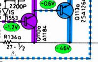 |
||
|
Poetry2me
Inventar |
#33
erstellt: 03. Jun 2022, 23:21
|
|
|
I think you found something, E marks the Emitter, middle pin is collector for most Japanese transistors. Leaves Basis pin to be opposite of E. - Johannes |
||
|
Elektronator
Stammgast |
#34
erstellt: 04. Jun 2022, 00:17
|
|
This is really an easy way. The base can be found with a simple diode tester. Some Multimeter have a socket for transistor test. The display shows the current gain. With correct connection the current gain is higher than with interchanged collector and emitter. If you have no diode or transistor tester but a voltage source (e.g. 20 V), a resistor (e.g. 10 kOhm) and a current indicator (ampere meter or LED) you can check the diodes reverse breakdown voltage. BE Diode: Breakdown voltage about 9 V (2SA1184: Ueb > 5 V) 9 V is similar to most of the bipolar silicon transistors BC Diode: Breakdown voltage see datasheet (2SA1184: Ucb > 120 V) |
||
|
Nidexx
Ist häufiger hier |
#35
erstellt: 04. Jun 2022, 10:42
|
|
|
Thank You Gentlemen This can be a Difficult project I have not replaced capacitors .and dont Know much about the Amplifier .. I bought it ON line many years ago.And it did not work on one channel So I took Out Q 111 both sides and measured it many times I cannot find anything wrong with them. Started to measure in stage 2 .. On the topmost Transistor Q 108 have ( about ) + 45 2 sides base and emitter -45 on collector appeared wrong ( - 45 ) so I soldered out ( At the end ) all transistors in that stage seems OK The control Bulb lamp Lit up and there was a short before i Tested the transistors Q105 Q 104 above. Then I Powered down and tried to Think .. Have not tested anything about the Bulb Coming on I dont have any experience but my Position at this moment is that -45 on Q108 is wrong but transistors and effekt resistors R132 and R133 are not open .I have not measured actual values. I may be wrong here please disregard if wrong but if some components value is off say fex R132 rises -- the Voltage difference base -emitter is such that the Transistor wont open Making it a Quantitative problem rather than a Qualitative ( On / OFF 1 or 0 ) Before all this I measured on the stage 4 and I could not notice any upsetting values the value on Q 111 one side was off -0.65 all pins but nothing evidently wrong.otherwise. the -45 V on collector Q108 .I believe is something to work on -- feel free to correct :Some head scratching going on here And the lit Lamp Bulb finding I did find one or 2 circuit traces that did not connect to the Component. Is it a must replace alla capacitors before even try to continue.? |
||
|
Poetry2me
Inventar |
#36
erstellt: 04. Jun 2022, 12:04
|
|
|
Maybe the problem is not to be found in components but rather in solder joints or copper tracks which may have invisible cracks. One problem I came across multiple times in Luxman L-xxx amps were bad solder joints at LEDs and transistors. Explanation could be that if parts are pushed in before originally soldered, the pins are under tension and will continue to work when repeatedly heated and cooled down again in operation. As a consequence, solder will develop thin cracks and increasingly cause problems when under mechanical or electric stress. 40 years of usage leave traces. Again, especially the LEDs and transistors in TO126 housing (L-410) seem to develop problems since these may heat up more than we think and their legs are under tension. Try re-soldering and search for problems with the copper tracks like cracks etc. When measuring, it is indeed a good idea to follow the DC path from +rail to -rail with stage 2 (red) and later stages. Also follow the DC path left of stage 2 with the diodes and the LED. Each diode should have 0.6V measured across and the LED should have ca. 1.9V voltage drop. These hold the two transistor basis pins fixed at constant voltages. - Johannes [Beitrag von Poetry2me am 04. Jun 2022, 12:06 bearbeitet] |
||
|
Nidexx
Ist häufiger hier |
#37
erstellt: 06. Jun 2022, 19:13
|
|
|
Thank you Sir the solder joint inspection is something I will check I have a little less time currently I have an old motorcycle with electrical minor issues I am at the " planning " stage thinking about how I will proceed The transistors in stage 2 is out and I am pondering measure the other components before soldiering them ( Transistors ) in making it simpler to measure their values in circuit The resistors could be checked But how about the small capacitor C121a and other alike C126a Is there any way to check these small capacitors Preliminary with all components checked I solder in transistors Power up with light bulb and Stell-Transformator to see what happened when the bulb lit up if the Power transistors are shorted. I bought a couple of extras so worst case I can replace Luckily not the Super expensive ones Is it Possible to check capacitors in circuit with any device I have other HiFi amplifiers fex two identical Luxor Dirigent 8100 One sounds annoying god -- the other not so god .. 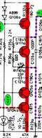 |
||
|
Poetry2me
Inventar |
#38
erstellt: 06. Jun 2022, 21:35
|
|
|
Measuring capacitors and resistors in-circuit: Im am afraid there is no reliable way to measure these components without at least lifting some of their legs. As I described above, using the lightbulb as current limiter on primary side makes it possible to switch on and do some live measurements of voltages between parts and find out where to look further. Regarding transistors in analog circuits: Most of them must have 0.6V (NPN, otherwise -0.6V respectively for PNP) Basis to Emitter in order to work correctly. When the circuit is turned on and you find B-E-Voltage <> 0.6V this is suspicious. - Johannes |
||
|
Nidexx
Ist häufiger hier |
#39
erstellt: 10. Jun 2022, 16:13
|
|
|
Gentlemen Sitting in the sun taking measurements Doing a chart of the values I have found that the diodes D104 b and D105 b seems short circuit. have not soldered them out yet. Not displaying any open circuit in no direction which the other side a ) does rather large resistance in forward direction and open in the back direction. Continuing measure if more has gone wrong downstream Please feel free tell if something obvious fries / Jan |
||
|
Poetry2me
Inventar |
#40
erstellt: 10. Jun 2022, 17:11
|
|
|
It is difficult for me to follow you in everything you are doing. Which of the amplifieres are you working on and which channel are you focussing on to fix? What das the lighbulb tell you? Is there a constant bright light or just a very low dim light? Are all parts soldered in when you turn on? Normally it makes no sense if you are removing parts and then turn on. - Johannes |
||
|
Elektronator
Stammgast |
#41
erstellt: 10. Jun 2022, 19:17
|
|
|
Hello Jan, A short-circuit of D104 or D105 or both will switch-off Q108. The collector voltage of Q108 will drop to about -45 V. All nodes at the power stage will drop to about -45 V. But this will cause no short-circuit. The incandescent lamp in series shall stay nearly dark. Do you really use a 500 W incandescent lamp? I assume this lamp causes no good protection. A 100 W lamp will provide better protection. It is difficult for me, too, to follow you in everything you are doing. Are you still working at L-400? Bernhard |
||
|
Nidexx
Ist häufiger hier |
#42
erstellt: 10. Jun 2022, 21:47
|
|
|
Thank you gentlemen, I appreciate your patience. It is somewhat trial and error for me .. I am on the 400 the 210 is working fine ..a bit better than that even. I was on a 100 W bulb alligator clips over the main fuse holder .( no trafo ) it worked for a while taking measurements Something shorted .. lit up the lamp bulb permanently ( maybe a measure probe fumble ) so switched off. As fast as I could .. trying to save the Power transistors . Was afraid something would get damaged or already have done so I had values that looked suspicious on Q 111 all the time And on Q 108 +45 on 2 pins and -45 on one Power off tried to check stage 2 taking out transistors no apparent fault Not measured all Resistors yet in stage 2 But Found the diodes d104 d105 b that have something wrong .I was able to find new ones at a store in town this evening. It feels plausible that the diodes have been faulty and caused the effect on Q 11 and Q 108 The plan now is to measure the rest of the resistors both channels stage 2 Check solder joints for cracks Solder out check the diodes And in with new. Solder in transistors that is out Q105 Q104 is out. And then Power up with the transformer + lamp ( 100 W ) slowly starting 5 - V gradually increase to see if the final transistors blew.. Those are easy to measure on at the heat sink back Measure in later stages if it looks OK . If it checks out -- back to the 100 W over the main fuse holder and normal power up. Thanks again / Jan |
||
|
Nidexx
Ist häufiger hier |
#43
erstellt: 11. Jun 2022, 02:07
|
|
|
Q113 a shorted Desoldered Q112 s and Q113 . s Short is then gone No LED s come on for 8 V will measure more .. Se what I have where / Jan |
||
|
Poetry2me
Inventar |
#44
erstellt: 11. Jun 2022, 08:51
|
|
|
No need to turn the device on right now. Work your way backwards through the stages measuring parts:
Blue Stage 4: Q112 and Q113 are the two power transistors in final (blue) stage 4. Such damage is not unususal if you have a power amp problem. Check the Emitter resistors R113a !!!!! In case of such fatal damage it is also likely that at least one of the over-current protection transistors Q106 and Q107 has sacrificed it's life, sometimes including surrounding parts. I have seen these explode at times. Violet Stage 3: It is likely you will find one or two defective driver transistors in (violet) stage 3. Also check R137 between the drivers !!! Red Stage 2: In case one of the drivers has burned through towards Base pin, there will be damage in one of the transistors of stage 2, including Q111 (quiescent current regulation) and next likely Q105. But check all of stage 2. - Johannes |
||
|
Nidexx
Ist häufiger hier |
#45
erstellt: 11. Jun 2022, 09:42
|
|
|
Thank you Sir Unless i shorted more for the trafo 8 V with bulb after it .. .I had no bulb glow to speak off. has not been powered up yet. fully. stage 2 is measured should be OK ( Both sides ) all parts except the small capacitor I dont know how to check and rarely goes wrong what I have read. the Q113 one is shorted. I believe I have a spare Would it be wrong to solder in a Q113 replacement start slowly with the trafo + bulb if I think right the LED s wont come on without the last transistors in After the basic checks described below in your last post.- in particular emitter Resistors R113 and a quick check downstream from the shorted Q 113 / Jan |
||
|
Poetry2me
Inventar |
#46
erstellt: 11. Jun 2022, 10:32
|
|
|
Don't set it under power unless you have found and replaced all defective parts. There is no sense in trying to power up amps with parts partially removed. It will not give you realistic information. Better try finding a replacement for the defective Q113. For proof of concept, even a transistor model not precisely the same can sometimes be used, just comparable in maximum values (voltages, currents, fT same or higher) for a start. As long as you are not running the amp with high signal or load, there is moderate risk. - Johannes [Beitrag von Poetry2me am 11. Jun 2022, 10:43 bearbeitet] |
||
|
Nidexx
Ist häufiger hier |
#47
erstellt: 12. Jun 2022, 10:00
|
|
|
I will try with the variable transformer and Bulb Reason being it is simpler measure Voltage --Being inexperienced like me .. where there are values to be found in the service manual. + LED diodes that come on evenly for a few Volts.if OK Starting slow 5 - 8 V Hopefully Stopping if something looks wrong.And if so have a better possibility to find it. Reason being I cannot figure out what component (s ) are defective measuring in circuit --this having so many Parallel Branches A resistor can even be Open ..and show values on the Multi meter .. A small capacitor is also not possible to check at all as far as I know.. It helps there are two sides .But I still find it difficult bordering to impossible. Should some component fry ( for the few Volts ) so be it. In with a new Q113 and check the emitter resistors that I get the impression can take some beating lets see. Then I will go for it. Thanks / Jan |
||
|
Poetry2me
Inventar |
#48
erstellt: 12. Jun 2022, 14:00
|
|
|
Checking resistors with low resistance values: Be aware that you will not get exact values with your standard multimeter when measuring anything below 1 or 2 Ohms. The reason is that contacts and cables used you use measuring will add to the resistance value the meter sees. Anyway, for the emitter resistors you will want to know if these are burned through or not (yes/no). Only rarely you will find resistors with moderately changed values. Most emitter resistors are simply a disconnect when damaged. [Beitrag von Poetry2me am 12. Jun 2022, 15:34 bearbeitet] |
||
|
Nidexx
Ist häufiger hier |
#49
erstellt: 13. Jun 2022, 02:22
|
|
|
New Q113 a Emitter resistors seems OK Did a proper job measure stage 2 ( when transistors was out ) and 4 when de soldered. Powered up ca 4.5 V with variable transformer. LED on a came on LED on b did not come on Voltages on stage 2 - 4 b Off not right Q110 b is shorted ... it can be the reason for high minus voltage into stage 2 Need to get a replacement and then a few Volts on --again see what happens. Thanks Jan |
||
|
Poetry2me
Inventar |
#50
erstellt: 13. Jun 2022, 08:11
|
|
|
Your current Luxman L-400 repair progress: Why don't you trust the lightbulb to protect your device? You could easily turn on full primary mains voltage 230V~. Only then you would see if voltages are right on left channel (all parts with "a" suffix) or if some short still draws high current (lightbulb stays on). Let us know the voltages along each stages path from rail to rail, especially the red stage 2. Regarding Q110b: You are obviously also measuring the right channel ("b" suffix). Hint: Buy some more of each transistor and also buy the complementary types. - Johannes |
||
|
Nidexx
Ist häufiger hier |
#51
erstellt: 13. Jun 2022, 09:21
|
|
|
Thank you Sir No I dont want to do that ( Full power just yet ) I have the variable transformer + light bulb after it. ( big one ) now and just a few Volts. I have yet to obtain even Voltage at both sides a and b Even if I dont get the right operating amplifier values for low Voltage.. As long as it is the same on both sides . I feel I am in a better Position. Perhaps I am Stubborn and Dumb But this being a hobby and having a learning curve. I can take it step vise . I did try the light bub 100 w and full power . Worked for a while Bulb lit up and stayed on and I later found a shorted power transistor. Darkness on LED s I did have LED s on at the circuit Board but the wrong Voltage on Q111. But had to start over again as I am doing now. Back to square one. I am thinking No power it wont fry components .Low power lesser risk . can be wrong .. But Physics and Electrics is so at times . 200 W into a 40 W Bulb Poff + darkness --40 W into a 200 W bulb :: It might not light up can still be darkness but it wont fry. I dont blame the 100 W bulb method. And I can be wrong Some transistor takes only 1.2 V on the base pin and I am applying 4.5 V already . So the plan is measure Q 112 Q 111 Q 113 Voltage on the heat sink getting those Voltages even and the same on both sides. even for low Voltage And even if they are out of spec. I believe the LED .s then come on for ca 5 V ..Then I can increase the Voltage .. still measuring Q 112 Q 111 Q 113 Transistor Voltages I have then some time to look for excessive heat somewhere touching and IR Thermometer. If I can reach operating value 45 V step vise with transformer -- With Even values on heat sink transistors both sides LED s on Evenly. I can then power down take away the transformer connect the 100 W Bulb and do the full power ON. If it fries again it can be the Electronic recycling bin a dark night. Thanks Again .Can take a while before I have the Components ( Transistor ) Perhaps measure some more on stage 3 and 4 Thanks / Jan |
||
| ||

|
|
||||
| Das könnte Dich auch interessieren: |
|
Luxman L 210 Problem! *Blackbeard616* am 13.03.2009 – Letzte Antwort am 16.03.2009 – 7 Beiträge |
|
Luxman L-210 Sholva am 15.06.2013 – Letzte Antwort am 17.06.2013 – 14 Beiträge |
|
Luxman L 210 Problem Homer_69 am 14.12.2021 – Letzte Antwort am 07.04.2023 – 49 Beiträge |
|
Luxman- L 400 ohne Musikleistung Schissi am 14.11.2016 – Letzte Antwort am 15.11.2016 – 6 Beiträge |
|
Luxman L-210, mal wieder was "Neues" blademage am 25.08.2020 – Letzte Antwort am 02.11.2020 – 35 Beiträge |
|
Luxman L-113A Homer_69 am 03.04.2022 – Letzte Antwort am 08.04.2022 – 13 Beiträge |
|
Luxman L-400 Birnen wechseln - alle tot toddrundgren am 07.08.2013 – Letzte Antwort am 08.08.2013 – 2 Beiträge |
|
Luxman L-410 defekt motoerhead68 am 30.12.2004 – Letzte Antwort am 04.01.2005 – 14 Beiträge |
|
Luxman L-410 Ruhestrom woz am 02.10.2007 – Letzte Antwort am 03.10.2007 – 4 Beiträge |
|
Luxman L-410 Aussetzer earny22 am 18.02.2008 – Letzte Antwort am 09.03.2008 – 6 Beiträge |
Anzeige
Produkte in diesem Thread


Aktuelle Aktion


Partner


Top 10 Threads in Hifi-Klassiker der letzten 7 Tage
- Kondensator ersetzen mit höherem Wert - zulässig?
- WD40 als Kontaktspray?
- Grundig R-2000 Mutingproblem
- Entstörkondensator- Beschriftung und deren Bedeutung
- Dreh - Lautstärkeregler defekt? reagiert falsch oder gar nicht Aiwa NSX AV 320
- Problem bei Reparatur von Pioneer CT 676
- Marantz / Superscope CD-302A Tape Deck
- "Tapedeck-Reparatur" Thread
- Welche Glassicherungen/Feinsicherungen Flink oder Träge ?
- Akai GX-260D-Überholung, Transistorersatztypen?
Top 10 Threads in Hifi-Klassiker der letzten 50 Tage
- Kondensator ersetzen mit höherem Wert - zulässig?
- WD40 als Kontaktspray?
- Grundig R-2000 Mutingproblem
- Entstörkondensator- Beschriftung und deren Bedeutung
- Dreh - Lautstärkeregler defekt? reagiert falsch oder gar nicht Aiwa NSX AV 320
- Problem bei Reparatur von Pioneer CT 676
- Marantz / Superscope CD-302A Tape Deck
- "Tapedeck-Reparatur" Thread
- Welche Glassicherungen/Feinsicherungen Flink oder Träge ?
- Akai GX-260D-Überholung, Transistorersatztypen?
Top 10 Suchanfragen
Forumsstatistik
- Registrierte Mitglieder931.209 ( Heute: 8 )
- Neuestes MitgliedHondo314
- Gesamtzahl an Themen1.564.960
- Gesamtzahl an Beiträgen21.873.252
